/
Gooch and house go Gooch and house go

Gooch and house go - PDF document

danika-pritchard
danika-pritchard . @danika-pritchard
Follow
391 views
Uploaded On 2017-03-29

Gooch and house go - PPT Presentation

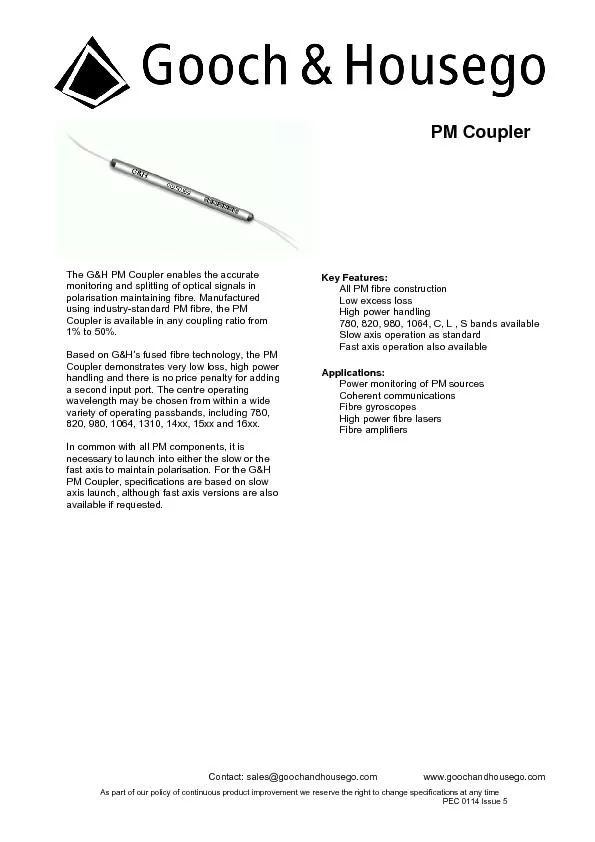
The GH PM Coupler enables the accurate monitoring and splitting of optical signals in polarisation maintaining fibre Manufactured using industrystandard PM fibre the PM Coupler is available in any ID: 332449

The G&H Coupler enables

Share:

Link:

Embed:

Download Presentation from below link

Download Pdf The PPT/PDF document "Gooch and house go" is the property of its rightful owner. Permission is granted to download and print the materials on this web site for personal, non-commercial use only, and to display it on your personal computer provided you do not modify the materials and that you retain all copyright notices contained in the materials. By downloading content from our website, you accept the terms of this agreement.


Presentation Transcript

Contact: sales@goochandhousego.com www.goochandhousego.com As part of our policy of continuous product improvement we reserve the right to change specifications at any time PEC 0114 Issue 5 The G&H PM Coupler enables the accurate monitoring and splitting of optical signals in polarisation maintaining fibre. Manufactured using industry-standard PM fibre, the PM Coupler is available in any coupling ratio from Based on G&H’s fused fibre technology, the PM Coupler demonstrates very low loss, high power handling and there is no price penalty for adding a second input port. The centre operating wavelength may be chosen from within a wide variety of operating passbands, including 780, 820, 980, 1064, 1310, 14xx, 15xx and 16xx. In common with all PM components, it is necessary to launch into either the slow or the fast axis to maintain polarisation. For the G&H PM Coupler, specifications are based on slow axis launch, although fast axis versions are also available if requested. Key Features: All PM fibre construction  Low excess loss  High power handling  780, 820, 980, 1064, C, L , S bands available  Slow axis operation as standard  Fast axis operation also available Applications:  Power monitoring of PM sources  Coherent communications  Fibre gyroscopes  High power fibre lasers  Fibre amplifiers PM Coupler | 2 Contact: sales@goochandhousego.com www.goochandhousego.com As part of our policy of continuous product improvement we reserve the right to change specifications at any time PEC 0114 Issue 5Parameter Specification Unit Centre Wavelength Range 7xx 8xx 9xx 10xx 11xx 1310 14xx 15xx 16xx nm Available Wavelengths1000 -1099 1100 -1199 1310 1425 -1499 1500 -1599 1600 -1650 Coupling Ratio Coupling Ratio Tolerance +/- 0.5 % Grade A 20 20 20 20 20 20 20 dB Extinction RatioGrade B 17 17 17 17 17 17 17 17 17 dB Coupling Ratio Coupling Ratio Tolerance +/- 1.5 % Extinction Ratio Grade A 20 20 20 20 20 20 20 dB Grade B 17 17 17 17 17 17 17 17 17 dB Coupling Ratio Coupling Ratio Tolerance +/- 3.0 % Extinction Ratio Grade A 20 20 20 20 20 20 20 dB Grade B 17 17 17 17 17 17 17 17 17 dB Coupling Ratio Coupling Ratio Tolerance +/- 4.0 % Extinction Ratio Grade A 17 17 20 20 20 20 dB Grade B 15 15 15 15 15 17 17 17 17 dB Coupling Ratio Coupling Ratio Tolerance +/- 5.0 % Extinction Ratio Grade A 17 17 20 20 20 20 dB Grade B 15 15 15 15 15 17 17 17 17 dB Excess Loss Grade A 0.3 0.3 0.3 0.3 0.3 0.3 dB Grade B 0.5 0.5 0.5 0.5 0.5 0.5 0.5 0.5 0.5 Return Loss/Directivity 50 dB Optical Power Handling 4 W Pigtail Tensile Load 5 N Operating Temperature -5 to +75 Storage Temperature -40 to +85 Fibre Type Polarisation maintaining fibre (industry-standard profile) 1. All specifications are for operation at room temperature. 2. The centre wavelength may be selected from within the available wavelength ranges supplied. 3. Defined for signal path P1-P2. 4. Defined for both signal path P1-P2 and tap path P1-P3. 5. Fibre Single mode cut-off 6. For operation at powers of greater than 4W the component housing and fibre must be adequately heat-sunk (for additional information contact G&H Sales). Components intended for high power operation are only available in the 2x2 configuration. Component performance and reliability under high power must be determined within the customer system. 7. The performance and reliability of optical connectors is not guaranteed for optical powers of greater than 1W. 8. For connectorised component, operating temperature range is –5 to +75C. Housing Code Description 1x2, 2x2 Dimensions (mm) Pigtail 3 Regular 3.0 (Ø) x 60 (L) Primary-coated fibre 5 Semi-ruggedised Slim 3.0 (Ø) x 76 (L) Ø 0.9 mm loose-tube 7 High Power Housing 5 (W) x 5 (H) x 85 max (L) Primary-coated fibre C Regular High Power 3.0 (Ø) x 60 (L) Primary-coated fibre