/
Multi-stage transistor amplifiers Multi-stage transistor amplifiers

Multi-stage transistor amplifiers - PowerPoint Presentation

danya
danya . @danya
Follow
68 views
Uploaded On 2023-11-08

Multi-stage transistor amplifiers - PPT Presentation

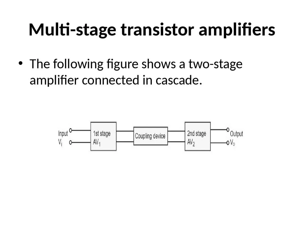
The following figure shows a twostage amplifier connected in cascade The overall gain is the product of voltage gain of individual stages AVAV1AV2 V2V1V0V2V0V1 Where A V   Overall gain A ID: 1030588

coupled amplifier stage gain amplifier coupled gain stage voltage frequency frequencies transformer transistor coupling capacitor stages high reactance impedance

Share:

Link:

Embed:

Download Presentation from below link

Download Presentation The PPT/PDF document "Multi-stage transistor amplifiers" is the property of its rightful owner. Permission is granted to download and print the materials on this web site for personal, non-commercial use only, and to display it on your personal computer provided you do not modify the materials and that you retain all copyright notices contained in the materials. By downloading content from our website, you accept the terms of this agreement.


Presentation Transcript

1. Multi-stage transistor amplifiersThe following figure shows a two-stage amplifier connected in cascade.

2. The overall gain is the product of voltage gain of individual stages.AV=AV1×AV2 V2/V1×V0/V2=V0/V1Where AV = Overall gain, AV1 = Voltage gain of 1st stage, and AV2 = Voltage gain of 2nd stage.If there are n numbers of stages, the product of voltage gains of those n stages will be the overall gain of that multistage amplifier circuit.

3. Amplifier ConsiderationFor an amplifier circuit, the overall gain of the amplifier is an important consideration. To achieve maximum voltage gain, let us find the most suitable transistor configuration for cascading.CC Amplifier Its voltage gain is less than unity. It is not suitable for intermediate stages.CB Amplifier Its voltage gain is less than unity. Hence not suitable for cascading.

4. CE Amplifier Its voltage gain is greater than unity. Voltage gain is further increased by cascading. The characteristics of CE amplifier are such that, this configuration is very suitable for cascading in amplifier circuits. Hence most of the amplifier circuits use CE configuration.

5. RC Coupling AmplifierThe resistance-capacitance coupling is, in short termed as RC coupling. This is the mostly used coupling technique in amplifiers.

6. Construction of a Two-stage RC Coupled AmplifierThe constructional details of a two-stage RC coupled transistor amplifier circuit are as follows. The two stage amplifier circuit has two transistors, connected in CE configuration and a common power supply VCC is used. The potential divider network R1 and R2 and the resistor Re form the biasing and stabilization network. The emitter by-pass capacitor Ce offers a low reactance path to the signal.

7. The resistor RL is used as a load impedance. The input capacitor Cin present at the initial stage of the amplifier couples AC signal to the base of the transistor. The capacitor CC is the coupling capacitor that connects two stages and prevents DC interference between the stages and controls the shift of operating point. 

8. Frequency Response of RC Coupled AmplifierFrequency response curve is a graph that indicates the relationship between voltage gain and function of frequency. The frequency response of a RC coupled amplifier is as shown in the following graph.From the graph, it is understood that the frequency rolls off or decreases for the frequencies below 50Hz and for the frequencies above 20 KHz. whereas the voltage gain for the range of frequencies between 50Hz and 20 KHz is constant. Following equation means that the capacitive reactance is inversely proportional to the frequency.Xc=1/2πfc

9. At Low frequencies (i.e. below 50 Hz)The capacitive reactance is inversely proportional to the frequency. At low frequencies, the reactance is quite high. The reactance of input capacitor Cin and the coupling capacitor CC are so high that only small part of the input signal is allowed. The reactance of the emitter by pass capacitor CE is also very high during low frequencies. Hence it cannot shunt the emitter resistance effectively. With all these factors, the voltage gain rolls off at low frequencies.

10. At High frequencies (i.e. above 20 KHz)Again considering the same point, we know that the capacitive reactance is low at high frequencies. So, a capacitor behaves as a short circuit, at high frequencies. As a result of this, the loading effect of the next stage increases, which reduces the voltage gain. Along with this, as the capacitance of emitter diode decreases, it increases the base current of the transistor due to which the current gain (β) reduces. Hence the voltage gain rolls off at high frequencies.

11. At Mid-frequencies (i.e. 50 Hz to 20 KHz)The voltage gain of the capacitors is maintained constant in this range of frequencies, as shown in figure. If the frequency increases, the reactance of the capacitor CC decreases which tends to increase the gain. But this lower capacitance reactive increases the loading effect of the next stage by which there is a reduction in gain.Due to these two factors, the gain is maintained constant.

12. Advantages of RC Coupled AmplifierThe following are the advantages of RC coupled amplifier.The frequency response of RC amplifier provides constant gain over a wide frequency range, hence most suitable for audio applications.The circuit is simple and has lower cost because it employs resistors and capacitors which are cheap.It becomes more compact with the upgrading technology.

13. Disadvantages of RC Coupled AmplifierThe following are the disadvantages of RC coupled amplifier.The voltage and power gain are low because of the effective load resistance.They become noisy with age.Due to poor impedance matching, power transfer will be low

14. Applications of RC Coupled AmplifierThe following are the applications of RC coupled amplifier.They have excellent audio fidelity over a wide range of frequency.Widely used as Voltage amplifiersDue to poor impedance matching, RC coupling is rarely used in the final stages.

15. Transformer Coupled AmplifierWe have observed that the main drawback of RC coupled amplifier is that the effective load resistance gets reduced. This is because, the input impedance of an amplifier is low, while its output impedance is high.When they are coupled to make a multistage amplifier, the high output impedance of one stage comes in parallel with the low input impedance of next stage. Hence, effective load resistance is decreased. This problem can be overcome by a transformer coupled amplifier.In a transformer-coupled amplifier, the stages of amplifier are coupled using a transformer. Let us go into the constructional and operational details of a transformer coupled amplifier.

16. Construction of Transformer Coupled AmplifierThe amplifier circuit in which, the previous stage is connected to the next stage using a coupling transformer, is called as Transformer coupled amplifier.The potential divider network R1 and R2 and the resistor Re together form the biasing and stabilization network.

17. The emitter by-pass capacitor Ce offers a low reactance path to the signal. The resistor RL is used as a load impedance. The input capacitor Cin present at the initial stage of the amplifier couples AC signal to the base of the transistor. The capacitor CC is the coupling capacitor that connects two stages and prevents DC interference between the stages and controls the shift of operating point.This transformer coupling provides good impedance matching between the stages of amplifier. The transformer coupled amplifier is generally used for power amplification.

18. Frequency Response of Transformer Coupled AmplifierThe figure below shows the frequency response of a transformer coupled amplifier. The gain of the amplifier is constant only for a small range of frequencies. The output voltage is equal to the collector current multiplied by the reactance of primary.At low frequencies, the reactance of primary begins to fall, resulting in decreased gain. At high frequencies, the capacitance between turns of windings acts as a bypass condenser to reduce the output voltage and hence gain.So, the amplification of audio signals will not be proportionate and some distortion will also get introduced, which is called as Frequency distortion

19. Advantages of Transformer Coupled Amplifier.The following are the advantages of a transformer coupled amplifier −An excellent impedance matching is provided.Gain achieved is higher.There will be no power loss in collector and base resistors.Efficient in operation.

20. Disadvantages of Transformer Coupled AmplifierThe following are the disadvantages of a transformer coupled amplifier −Though the gain is high, it varies considerably with frequency. Hence a poor frequency response.Frequency distortion is higher.Transformers tend to produce hum noise.Transformers are bulky and costly.

21. ApplicationsThe following are the applications of a transformer coupled amplifier −Mostly used for impedance matching purposes.Used for Power amplification.Used in applications where maximum power transfer is needed.

22. Direct Coupled AmplifierAs no coupling devices are used, the coupling of the amplifier stages is done directly and hence called as Direct coupled amplifier.which is especially used to amplify lower frequenciessuch as amplifying photo-electric current or thermo-couple current or so.ConstructionThe output of first stage transistor T1 is connected to the input of second stage transistor T2.

23. The transistor in the first stage will be an NPN transistor, while the transistor in the next stage will be a PNP transistor and so on. This is because, the variations in one transistor tend to cancel the variations in the other. The rise in the collector current and the variation in β of one transistor gets cancelled by the decrease in the other.

24. AdvantagesThe advantages of direct coupled amplifier are as follows.The circuit arrangement is simple because of minimum use of resistors.The circuit is of low cost because of the absence of expensive coupling devices.DisadvantagesThe disadvantages of direct coupled amplifier are as follows.It cannot be used for amplifying high frequencies.The operating point is shifted due to temperature variations.ApplicationsThe applications of direct coupled amplifier are as follows.Low frequency amplifications.Low current amplifications.