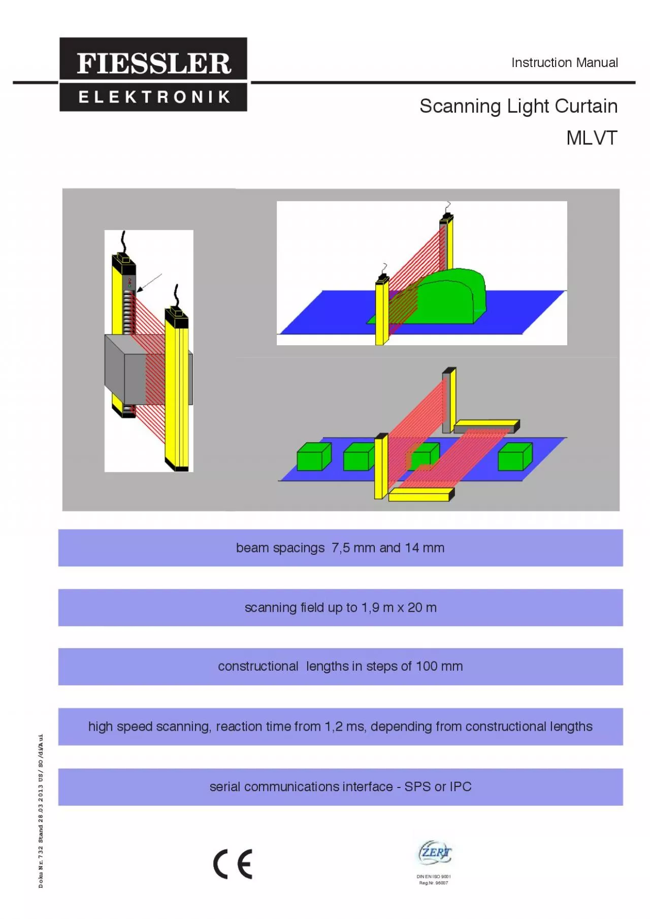
/
Scanning Light CurtainMLVT Scanning Light CurtainMLVT

Scanning Light CurtainMLVT - PDF document

danya
danya . @danya
Follow
342 views
Uploaded On 2022-09-01

Scanning Light CurtainMLVT - PPT Presentation

FIESSLER E L E K T R O N I K Instruction Manual DIN EN ISO 9001RegNr 96007 Doku Nr 732 Stand 28032013 US SOdiAui sectionContents1 Functional principle2Application areas31operational data32 ID: 945719

output data eye covered data output covered eye byte mlvt mode stand 108 116 118 732 doku eyes operating

Share:

Link:

Embed:

Download Presentation from below link

Download Pdf The PPT/PDF document "Scanning Light CurtainMLVT" is the property of its rightful owner. Permission is granted to download and print the materials on this web site for personal, non-commercial use only, and to display it on your personal computer provided you do not modify the materials and that you retain all copyright notices contained in the materials. By downloading content from our website, you accept the terms of this agreement.


Presentation Transcript

Scanning Light CurtainMLVT FIESSLER E L E K T R O N I K Instruction Manual DIN EN ISO 9001Reg.Nr. 96007 Doku Nr. 732 Stand 28.03.2013 US/ SO/di/Aui sectionContents1. Functional principle2.Application areas3.1operational data3.2 physical dimensions 3.3scanning area, resolution, order codes4.Commissioning 4.1mounting and adjustment 4.3 pin configuration 4.4 connection examples 4.4.2 several MLVTs in a network4.5 function test5.Operating modes (mensuration data scanning)5.1operating mode „number of covered eyes“5.2operating mode „topmost covered eye“5.3operating mode „lowest (bottom) covered eye"5.4operating mode „status of all eyes as reference bit pattern“5.5 operating mode „first free eye“5.6example of data displaying6.Different ways of data output (communication)6.1defined data output by random requisition byte6.2data output depending on requisition byte 6.3defined data output by defined requisition byte6.4permanent data output (polling)7.Programming7.1preparation7.2short description of re-programming 7.3detailed description of re-programming procedures7.3.2data output depending on requisition byte 7.3.3permanent data output 7.3.4defined data output by defined requisition byte8.Serial interface8.1RS 4858.1.2bus system8.1.3pin conf

iguration 8.2RS 232 protocol9.Cleaning10.Summarization of specifications11.Appendix11.1conversion table 2 Table of Contents Doku Nr. 732 Stand 2.7.2003 US/ SO/di Doku Nr. 732 Stand 28.03.2013 US/ SO/di/Aui 1. Function PrincipleThe transmitter generates infrared light beams that are permanently flashing at high speed. The parallel light beams (beamspacing 7,5mm or 14 mm) are evaluated in the receiver in synchronous action with the transmitter. This evaluation of the beamsto thetransmitter by means of a so-called synchronizing eye, which is located within the scanning field on the plug end of the unitsschecking, a monitoring of the current status of all eyes is carried out. The obtained data are ready to be retrieved via the serialinterface. The presence on any obstacle within the scanning field will activate both receiver outputs. 2. Areas of ApplicationThe scanning light curtain MLVT scans and measures non-transparent objects that are placed within the scanning field. Due tos(numbers of covered eyes, first (topmost) covered eye, lowest (bottom) covered eye, first free eye, status of all eyes as referen-ce bit pattern). The obtained data are produced via an RS 485 interface on demand or by permanent data output. 3 1. Function Principle and 2. Application

Areas synchronizing eyetransmitterreceiver Doku Nr. 732 Stand 2.7.2003 US/ SO/di Doku Nr. 732 Stand 28.03.2013 US/ SO/di/Aui 3.1 Operational DataThe scanning light curtains MLVT are characterized by the following features:- beam spacing only 7,5mm (0,29 in.)ty 0,5A/24V)- protective sytem IP 653.2 Physical DimensionsMLVT housings (transmitter and receiver)Aluminium profile, plastic coated RAL 1020 yellow, end pieces made from non-corrosive, spherically reinforced plastic (polyamide). Plexiglasslight outlet and inlet, optionally available with solvet-resistant silicate glass windows.The required scanning field heights can be looked up in table in section 3.3. 4 3. Features 26 mm 61 mm 23 mm PG 9 11 mm SLVTE EmpfängerSLVT Receiver/Récepteur FIESSLER E L E K T R O N I KD-73734 Esslingen, Kastellstr.90711/91 96 97 -0 1234567Made in Germany7: 24VDC ±20%6: 0V2: Ausg. unt.1: Ausg. frei PNP, 500mAadjustment àjustementLC interrupt interrompu LS freiLC free libre scanningfield height (mm) constructional length (mm) Minimum ndstancebetween fasteningsBFA(mm) 19962036 scanning field heightconstructional lengthsliding fastening brackets Insulating plastic layers and rings provided as additional insets to be mounted at the receiver brackets. These enhance the electromagn

eticcompatilbility of the MLVT when it is used in an area where electromagnetic interferences may occur. omponente „Bild S4R23Typ „TIFF“01140017.tif minimum distance between faste-nings BFA Doku Nr. 732 Stand 2.7.2003 US/ SO/di Doku Nr. 732 Stand 28.03.2013 US/ SO/di/Aui 3.3 Scanning Area dimensions, Resolution, Order Codes 5 3. Features out-puts.** maximum response time from alteration of scanning field until data output resolution 14 mm resolution 30 mm scanningfield height(mm) constr.length(mm) order coderange 7 m * response time ofswitching outputs("worst Case")in ms * * availability of obtained data("worst Case")in ms order codesrange 24 m * response time ofswitching outputs(worst Case)in ms * * availability ofobtained data (worstCase)in ms 19001996MLVT1900 / 24710,320,6MLVT1900 / 1335,9 Doku Nr. 732 Stand 2.7.2003 US/ SO/di Doku Nr. 732 Stand 28.03.2013 US/ SO/di/Aui 4.3 Mounting of transmitter and receiver When installing the transmitter and receiver of the MLVT, it must be ensured that the connectors of both devicesare located at the same side. Transmitter and receiver must be installed with parallel faces.Attachment and adjustment The supplied fastening brackets serve for the attachment and the adjustment of the light barrier. Together with thes

hifting tenon blocks, the brackets enable a multi-functional attachment.Rubber-metal connectionIn the event of intense vibrations, please use rubber-metal connections which can be obtained as optional 6 4. Commissioning installation with parallel faces In order to ensure an error-free operation, both the transmitter and the receiver devi-ces must be attached to stable, distortion-free and face-parallel constructions. Install the fastening brackets in a way that the adjusting screws remain easily accessi-Make sure that the shape of the housing profile is not distorted. Otherwise a perfect optical adjust-ment will not be possible. Adjust one fastening bracket whilst the adjusting screws on the other fa- adjustment screws with counter nuts for swivelling along longitudinal and lateral axis curtain longitudinalaxis lateral axis Swivelling along the longitudinal and lateralaxis Insulating plastic layers and rings provided as additional insets to be mounted at the receiver brackets. These enhance the electromagneticcompatilbility of the MLVT when it is used in an area where electromagnetic interferences may occur. omponente „Bild S6R23Typ „TIFF“01140017.tif Doku Nr. 732 Stand 2.7.2003 US/ SO/di Doku Nr. 732 Stand 28.03.2013 US/ SO/di/Aui 4.2 ConnectorsThe prod

uct standard of the series MLVT includes an extra flat plug-in connector that is located in the connectionlid. Its cover may be removed without cutting the connection cable plug. The housing itself remains tightly closed.4.3 Pin configurationThe connection is carried out according to the following diagram. The non-equivalent PNP-ports are short-circuit-safe and canbe connected independently from each other. s notconducting.Serial port RS485: 2-core cable simplex connection. Connection 3 is B ( + ), connection 4 is A ( - ).Caution!Ports 3 and 4 are no fail-safe outputs. 7 4. Commissioning 123456 123456 23 134567 1234567 PNP, 500mA connection lid with plug-in screw terminals. receiver 7-pins, transmitter 3-pins.DIP-Switches (Terminal) 7654321123 +24V DC±20% +24V DC±20% 1234567 ErdeErdeunbelegt SPSAusg. Unterbr.Ausg. FreiK2 (-) RS 485(+) RS 485 Doku Nr. 732 Stand 2.7.2003 US/ SO/di functional ground 4.4.1 MLVT as single systemOur connection example shows one MLVT receiver connected either to an SPC, or to a profibus gateway, or to an interfaceconverter. A termination (see section 8.1.3) is urgently required when using the RS485 connection. The MLVT (receiver) there-At the other side of the MLVT, where the SPC, the "Profibus Gateway" or the interface con

verter are connected, there is anot-her terminating network that can be hooked up. If not, an external network (see below) must be elaborated. 4.4.2 Several MLVTs in a networkAnother example shows several MLVTs connected to an SPC, to a Gateway profibus, or to an interface converter. 8 4. Commissioning Doku Nr. 732 Stand 2.7.2003 US/ SO/di MLVT receiver ted 4.5 Function Test For the initial commissioning it is sufficient to provide a voltage of 24V DC +/-20% for both transmitter and receiver. If the adjustment procedure has been carried out correctly (see section 4.1), the green LED at the receiver and the orange-co-tLED). In order to dispose of a certain light reserve, (the presence of dirt on the plexiglass windows may lead to a certain weake-ning of the scanning signal) it is in any case imperative to adjust the devices in a way that the orange LED at the receiver will ex-tinguish and only the green LED lights up.ld isfree. just-ment of both devices is carried out correctly (see section 4.1). 9 4. Commissioning D-73734 Esslingen, Kastellstr.90711/91 96 97 -0TLVT Transmitter/EmetteurBWS Typ2, ESPE Type2, ESPS Type2 E L E K T R O N I KSender ein TLVTS SenderTransmitter onEmetteur en marche 3: 123 Made in Germany1: TLVTE EmpfängerD-73734 Esslinge

n, Kastellstr.90711/91 96 97 -0TLVT Receiver/RécepteurBWS Typ2, ESPE Type2 , ESPS Type2 E L E K T R O N I K 1234567 PNP, 500mAadjustment àjustementLC interrupt interrompu LS freiLC free libre Doku Nr. 732 Stand 2.7.2003 US/ SO/di Doku Nr. 732 Stand 28.03.2013 US/ SO/di/Aui 5.1 operating mode „number of covered eyes“All covered receiver elements (=eyes) are counted and added, regardless of the number of objects placed into the scanning fieldor their positions within the field. Our example shows two objects placed in the scanning field, covering a total of 10 eyes.Select this operating mode for e.g. the mensuration of the dimensions of an object. Combined to a second MLVT, even two-di-mensional measurements are possible.5.2 operating mode „topmost eye covered“This mode displays only the position of the topmost covered eye. (the highest of all numbers of the covered eyes). The numbe- This mode is selected for special applications during levelling or contour scans. 10 5. Operating Modes 1 20 19 18 17 6 + 4 = 10 eyes covered Doku Nr. 732 Stand 2.7.2003 US/ SO/di Doku Nr. 732 Stand 28.03.2013 US/ SO/di/Aui 5.3 operating mode „lowest (bottom) covered eye“This mode displays only the position of the lowest covered

eye. (smallest of all numbers of the covered eyes). 5.4 operating mode „status of all eyes as reference bit pattern“This mode displays the conditions of all eyes along with their respective positions. Depending on the length of the light barrier,more than one byte can be obtained as a result. One after the other, the obtained results are transmitted byte perbyte as bitt eye.The second byte represents the positions of the next 8 eyes, i.e. eyes number 9 through 16, and so on. If, for the representa-tion of the last eyes, no complete byte is needed, the remaining bits are addressed as "0".Example: MLVT receiver 600/78As a practicable application, the scanning of a grid-shaped object is possible. 11 5. Operating Modes Doku Nr. 732 Stand 2.7.2003 US/ SO/di mensuration reading output= number of this special beam covered number of eyes= 10d (d = decimal code)topmost covered eye = 30dlowest covered eye= 21dfirst free (=uncovered) eye= 1dall eyes= 00111111b (b = binary code), 11000000b, 00001111b, 11111111b, 11111111b 12 5. Operating Modes Doku Nr. 732 Stand 2.7.2003 US/ SO/di synchronizing eye The MLVT produces the obtained mensuration readings via a serial interface (RS 485). As option, these light curtains can beconnected via an external converter to

a serial RS 232 interface, or to a profibus-DP fieldbus. The user may choose from diffe-rent operating and scanning modes, e.g. permanent output (polling mode) or data output via PC or SPC using one byte as re-6.1 Determined data output by using random requisition byte If there is no fixed value (byte) for the data transfer, this operating mode provides a special possibility for data output using arandomly chosen requisition byte. Our example shows the operating mode "number of covered eyes".6.2 data output on demand according to individual requisition bytesIf different mensuration procedures are carried out by the MLVT, this mode provides the possiblility to display the obtained dataof the various mensurations according to their individual requisition bytes. 13 6. Different ways of Data Output (Communication) Doku Nr. 732 Stand 2.7.2003 US/ SO/di byte randomlychosen, i.e. 128d 128d number of coveredeyes 64d lowest coveredeye 6.3 Determined data output by using pre-defined requisition byteThe RS485 interface is laid out as a bi-directional bus-system for up to 32 extensions. The user may apply up to 6 differentadresses in order to directly actuate the MLVT unitis. Here, hoewevewr, the operating mode " Status of all elements as referen-6.4 Permanent dat

a output (polling)This operating mode enables permanent data output without the use of any requisition byte. Here, hoewevewr, the operating 14 6. Different ways of Data Output (Communication) Doku Nr. 732 Stand 2.7.2003 US/ SO/di mensuration data requision byte 128 d mensuration data Doku Nr. 732 Stand 28.03.2013 US/ SO/di/Aui By using the different programming possibilities, the user may choose from 5 different modes of mensuration data coverage(operating modes) and 4 output modes, which will remain stored even after a power failure. Usually, the programming of the7.1 Preparation&#x-000;Any re-programming can be carried out by using a PC, with a serial terminal software and an interface converter (RS 232 ).7.2 Short description of re-programmingFirst of all, the MLVT requires the entry of the password as a 4-digit byte sequence (109d,108d,118d,116d). This can be car-ried out during the regular operation of the MLVT. However, if the light curtain has been previously set on "permanent data out-put" mode, " this can only be achieved after a voltage reset (short interruption of the power supply of the MLVT). t-ry procedure is carried out faulty or if the maximum allowable time period of 2,5 s is exceeded, the light curtain will automaticallyreturn to the pr

eviously programmed data output mode. Then the programming procedure must be repeated. 15 7. Programming Output possibilities of mensuration data total numberof covered ey-es (decimal value) topmost cove-red eye(decimal value) lowest (bottom)covered eye(decimal value) first free eye(decimal value) status of sllfree eyes as bitpattern(decimalvalue) requisition bytefor mensura-tion data output defined mensuration output by randomlychosen requisition byte mensuration data output : according to the 1281632--16-64-50--16--96- any byte (anycaracter) 128-3264 requisition byte determined mensuration output ----121718 by pre-defined requisition byte (address byte) 4133363763839--16-225152-165096-248249685354705556--250251-252253 permanent data output withoutrequisitionbyte 8407257-- The following 4 bytes are transmitted to the MLVT, the fifth byte (closing byte)taken from the data in this column defines the data output mode and terminatesthe re-programming procedure. 109,108,118,116, ... Doku Nr. 732 Stand 2.7.2003 US/ SO/di Doku Nr. 732 Stand 28.03.2013 US/ SO/di/Aui 7.3 Detailed description: re-programming Basic requirement is the presence of a communication link (as described in chapter 4.1). The MLVT program is pre-set on themensuration data output mode

"topmost covered eye, permanent data output". The RS 485 interface at the light curtain is laid-programming during operation (under permanent data output) is not possible. nin the center column of the tables shown in the following.eis used, the light curtain will automatically return to the previously programmed data output mode. Then the programming pro-lay-ed continuously. Our example shows the MLVT programmed to a determined data output (status of all eyes as reference bit pat-7.3.1 determined data output by any requisition byteThis output mode requires a pre-selection of the mensuration data to be displayed and its programming. The left column of thel by-te sequence (center column). One of these sequences is selected and transmitted to the MLVT for programming it. After that,the mensuration data can be retrieved by entering any non-defined (randomly chosen) byte as requisition byte. 16 7. Programming available mensuration data output possibili-ties status of all eyes as reference bit pattern required byte sequence for programming thedesired operating mode into the MLVT (decimal values) 109 108 118 116 96 requisition byte for men-suration data retrieval lowest (bottom) covered eye topmost covered eye total number of covered eyes firs

t free eye 109 108 118 116 64 109 108 118 116 32 any byte 109 108 118 116 128 109 108 118 116 50 Doku Nr. 732 Stand 2.7.2003 US/ SO/di receiver max. 2,5 s byte , e.g. 96 7.3.2 Data output depending on requisition byteThis operating mode permits the retrieval of the four mensuration data by using the corresponding requisition byte. For this pur-pose, the byte sequence shown in the center column of the table mentioned below is transmitted to the MLVT. Afterwards, the 7.3.3 Permanent data outputThis operating mode permits the permanent retrieval of the mensuration data without using any requisition byte. However, herethe operating mode "status of all eyes as reference bit pattern" is not possible. If a re-programming of the MLVT during selected operating mode "permanent data output" is needed, this can only be achievedafter a voltage reset (short interruption of the power supply of the MLVT). In this case, the allowable time period of 2,5 s bet-ween the programming of the first 4 characters (bytes) must not not exceed 2,5s.s ex-ceeded, or if a wrong byte is used, the light curtain will remain in the previously programmed data output mode and will returninto operational readibness. 17 7. Programming available mensuration data

output possibili-ties status of all eyes as reference bit pattern required byte sequence for programming thedesired operating mode into the MLVT (decimal values) requisition byte for men-suration data retrieval(decimal values) 96 lowest (bottom) covered eye topmost covered eye total number of covered eyes first free eye 109 108 118 116 16 64 32 128 50 available mensuration data output possibili-ties total number of covered eyes required byte sequence for programming thedesired operating mode into the MLVT (decimal values) 109 108 118 116 8 permanent data outputwithout using any requisi-tion byte - topmost covered eye lowest (bottom) covered eye first free eye status of all eyes as reference bit pattern 109 108 118 116 40 109 108 118 116 72 - - 109 108 118 116 57 not available - - Doku Nr. 732 Stand 2.7.2003 US/ SO/di Doku Nr. 732 Stand 28.03.2013 US/ SO/di/Aui 7.3.4 Determined data output by pre-defined requisition byte (address byte)This operating mode is applied if the MLVT is operated in connection to a bus system with several extensions. Using this ope-rating mode it must be made sure that every single MLVT at the same bus is programmed to a different address in order to pro-gramming procedure

for defining mensuration data output. The following table provides the available mensuration data output 18 7. Programming available mensuration data output possibili-ties total number of covered eyes required byte sequence for programming theMLVT to the desired operating mode (decimal values) 109 108 118 116 12 requisition byte (byte ad-dress) for mensurationdata retrieval topmost covered eye lowest (bottom) covered eye first free eye total number of covered eyes 109 108 118 116 17109 108 118 116 22248109 108 118 116 51109 108 118 116 13 topmost covered eye lowest (bottom) covered eye first free eye total number of covered eyes 109 108 118 116 18109 108 118 116 23249109 108 118 116 52109 108 118 116 4 topmost covered eye lowest (bottom) covered eye first free eye total number of covered eyes 109 108 118 116 36109 108 118 116 68250109 108 118 116 53109 108 118 116 133 topmost covered eye lowest (bottom) covered eye first free eye total number of covered eyes 109 108 118 116 37109 108 118 116 69251109 108 118 116 54109 108 118 116 6 topmost covered eye lowest (bottom) covered eye first free eye total number of covered eyes 109 108 118 116 38109 108 118 116 70252109 108 118 116 55109 108 118 116 7 topmost covered eye l

owest (bottom) covered eye first free eye 109 108 118 116 39109 108 118 116 71253109 108 118 116 56 Doku Nr. 732 Stand 2.7.2003 US/ SO/di Doku Nr. 732 Stand 28.03.2013 US/ SO/di/Aui 8.1 RS 4858.1.1 InterfaceThe MLVT disposes of an RS 485 interface that enables an operation of the light barrier as a single system or within a bi-direc-tional bus system with up to 32 extensions (6 MLVT units) in half duplex mode. The serial data are transmitted in the form of voltage difference without ground relation via an inverted line (designated as "A"or "-") and a non-inverted line (designed as "B" or "+"). Between the two RS 485 outputs, an output level of +/- 2V is providedfor the transmitter. On the receiver, levels of +/- 200mV are still detected as valid signal. Due to the symmetrical transfer proce-dure, combined with a twisted pair cable, reliable linkages covering distances of up to 500 metres at high transmission speed8.1.2 Bus systemAs more than one transmitter are connected to one common line, only one data transmitter is activated at a time. This must bees.Single-line input bus systems always permit only half-duplex traffic, i.e. only one extension is allowed to transmit data. Only ifthe transmission procedure is completed, other extensions may r

esume transmitting.For data retrieval, 6 adresses are provided (248,249,250,251,252,253) for the MLVT. In order to avoid any unwanted data colli-sion, it must be made sure that every single address is assigned to only one MLVT only once, i.e. that no output data valuewill correspond to that value. The RS 485-standard defines only the electrical specifications, but no the transfer protocol. The MLVT uses the widely circula-ted RS232 interface protocol with the parameters 9600, N, 8, 1 .8.1.3 TerminationThe 2-cored RS 485 bus systems require the termination of the connection by using a terminating network which ensures a de-ienttermination for the RS 486 drivers. The cables should be laid out according to this resistor characteristics, i.e. they should havean impedance of 150 Ohms or higher.The MLVT (receiver) disposes of a DIP-switch (switch 1 set to ON) at the connector end. By using this switch, the termination at150 Ohms can be carried out.8.2 RS 232 ProtocolThe following diagram shows the progress of the signal for a data transfer at 9600 baud, 8 data bits, no parity pit, 1 stop bit.For the RS 232 protocol, only two states (low und high) apply. During the rest position, the line is high. The transmission start isindicated by the declining curve a

t the start bit. Then follow 8 data bits. The end of every transmission is indicated by a stop bit(always high). After each stop bit, the next start bit may follow immediately. At a transmission rate of 9600 baud, every single bitwill take 0,104166666ms, a complete data package will therefore need 1,04166666ms. 19 8. Serial Interface Doku Nr. 732 Stand 2.7.2003 US/ SO/di data bits bit 9. CleaningIn order to ensure an error-free operation of the MLVT (both receiver and transmitter), it is necessary to keep the front windowsclean at all times. If both the orange-coloured LED and the green LED at the receiver light up at the same time, even if the lightcurtain is perfectly adjusted and the scanning field is free, this might be a sign for possible dirty front windows. a-line solutions and provides limited chemical resistance against organic solvents. 10. Specification 20 9. Cleaning , 10. Specification Doku Nr. 732 Stand 2.7.2003 US/ SO/di Characteristic datascanning field height scanning field lengths(range) 100 mm … 1900 mm (according to number of beams) 0,1… 7 m, at a resolution of 14 mm 0,1… 24 m, at a resolution of 30 mm construction lengthsdefinitionnumber of beams reaction time/response time 196 mm … 1996 mm (according to number of beams)smallest

resolution 7,5 mm 7… 247 beams max. detection and reaction time = Minimum sojourn time of the object in the scanning field until response of out-puts.see table on page 5 Mechanical dataattachmentweight alminium profile, eloxal coated or yellow plastic coated RAL 1020, end pieces made of non-corrosive, sphericallyreinforced plastic (polyamide). Plexiglass light outlet and inlet, optional with solvent-resistant silicate glass. shifting fastening brackets on rear side of housing. transmitter: 0,45 kg to 4,5 kg depending on construction lengthreceiver: 0,5 kg to 5,0 kg depending on construction length Operating dataprotection class Operating ambient tempe-rature IP 65III-10 to 55 °C Storage temperature Electrical datacurrent draw-25 to 70 °C outputs (receiver) electric connection connecting cable Sender MLVTSEmpfänger MLVTE - integrated connector plug with PG9 as strain re-lief, alternatively conventional connector plug 3-cored, max. 0,75 mm2 output FREE and output Interrupted : failsafe PNP-outputs, max. 0,5 A, integrated connector plug with PG9 as strain relief, alternati-vely conventional connector plug 5-cored, max. 0,5 mm2 Doku Nr. 732 Stand 28.03.2013 US/ SO/di/Aui 11.1 Conversion tables 21 11. Appendix decimal (X10) hexadecimal(X16) binar

y code X2 ASCII code decimal (X10) hexadecimal(X16) binary code X2 ASCII code 000 001 00 01 0000 0000 0000 0001 NULL !064 065 40 41 0100 0000 0100 0001 @ A 002 003 02 03 0000 0010 0000 0011 04 0000 0100 0000 0101 "#066 067 $%068 069 42 43 0100 0010 0100 0011 44 0100 0100 0100 0101 B C D E 006 007 06 07 0000 0110 0000 0111 08 0000 1000 0000 1001 010 0A 0B 0000 1010 0000 1011 0C 0000 1100 0000 1101 &'070 071 (072 073 46 47 0100 0110 0100 0111 48 0100 1000 0100 1001 *+074 075 ,-076 077 4A 4B 0100 1010 0100 1011 4C 0100 1100 0100 1101 F G H I J K L M 014 015 0E 0F 0000 1110 0000 1111 10 0001 0000 0001 0001 018 12 13 0001 0010 0001 0011 14 0001 0100 0001 0101 ./078 079 0080 081 4E 4F 0100 1110 0100 1111 50 0101 0000 0101 0001 2082 083 4084 085 52 53 0101 0010 0101 0011 54 0101 0100 0101 0101 022 16 17 0001 0110 0001 0111 18 0001 1000 0001 1001 026 1A 1B 0001 1010 0001 1011 1C 0001 1100 0001 1101 67086 087 8088 089 56 57 0101 0110 0101 0111 58 0101 1000 0101 1001 :090 091 092 093 5A 5B 0101 1010 0101 1011 5C 0101 1100 0101 1101 N O P Q R T U V W X Z [ \ ] 030 031 1E 1E 0001 1110 0001 1111 20 0010 0000 0010 0001 034 0335 036 22 23 0010 0010 0010 0011 24 0010 0100 0010 0101 �?094 095 Leer ! 096 097 5E 5F 0101 1110 0101 1111 60 0110 0000 0110 0001 " # 098 099 $ %

100 101 62 63 0110 0010 0110 0011 64 0110 0100 0110 0101 038 26 27 0010 0110 0010 0111 28 0010 1000 0010 1001 042 2A 2B 0010 1010 0010 1011 2C 0010 1100 0010 1101 & ' 102 103 ( 104 105 66 67 0110 0110 0110 0111 68 0110 1000 0110 1001 * + 106 107 ' - 108 109 6A 6B 0110 1010 0110 1011 6C 0110 1100 0110 1101 ^ _ ' a b c d e f g h i j k l m 046 047 2E 2F 0010 1110 0010 1111 30 0011 0000 0011 0001 050 32 33 0011 0010 0011 0011 34 0011 0100 0011 0101 . / 110 111 0 112 113 6E 6F 0110 1110 0110 1111 70 0111 0000 0111 0001 2 114 115 4 116 117 72 73 0111 0010 0111 0011 74 0111 0100 0111 0101 054 36 37 0011 0110 0011 0111 38 0011 1000 0011 1001 058 3A 3B 0011 1010 0011 1011 3C 0011 1100 0011 1101 6 7 118 119 8 120 121 76 77 0111 0110 0111 0111 78 0111 1000 0111 1001 : 122 123 124 125 7A 7B 0111 1010 0111 1011 7C 0111 1100 0111 1101 n o p r s t u v w x y z { | } 062 063 3E 3F 0011 1100 0011 1111 &#x 000; ? 126 127 7E 7F 0111 1110 0111 1111 ~ \x7f Doku Nr. 732 Stand 2.7.2003 US/ SO/di Doku Nr. 732 Stand 28.03.2013 US/ SO/di/Aui FIESSLER 22 11. Appendix decimal (X10) hexadecimal(X16) binary code X2 ASCII code decimal (X10) hexadecimal(X16) binary code X2 ASCII code 191 BF 1011 1111 ¿255 FF 1111 1111 Doku Nr. 732 Stand 2.7.2003 US/ SO/di Doku Nr. 732 Stand 28.03.2013 US/