/
Mellanox Technologies Inc.         350 Oakmead Parkway, Sunnyvale, CA Mellanox Technologies Inc.         350 Oakmead Parkway, Sunnyvale, CA

Mellanox Technologies Inc. 350 Oakmead Parkway, Sunnyvale, CA - PDF document

debby-jeon
debby-jeon . @debby-jeon
Follow
378 views
Uploaded On 2016-03-23

Mellanox Technologies Inc. 350 Oakmead Parkway, Sunnyvale, CA - PPT Presentation

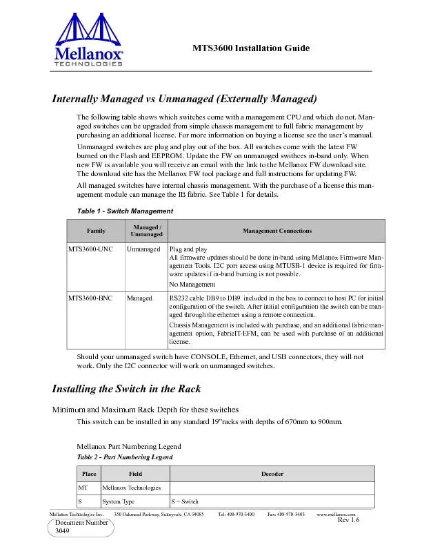
3049 Rev 16 Internally Managed vs Unmanaged Externally Managed The following table shows which switches come with a management CPU and which do not Managed switches can be upgraded from simple ch ID: 267020

3049 Rev 1.6 Internally Managed Unmanaged

Share:

Link:

Embed:

Download Presentation from below link

Download Pdf The PPT/PDF document "Mellanox Technologies Inc. 350 O..." is the property of its rightful owner. Permission is granted to download and print the materials on this web site for personal, non-commercial use only, and to display it on your personal computer provided you do not modify the materials and that you retain all copyright notices contained in the materials. By downloading content from our website, you accept the terms of this agreement.


Presentation Transcript

Mellanox Technologies Inc. 350 Oakmead Parkway, Sunnyvale, CA 94085 Tel: 408-970-3400 Fax: 408-970-3403 www.mellanox.com 3049 Rev 1.6 Internally Managed vs Unmanaged (Externally Managed) The following table shows which switches come with a management CPU and which do not. Man-aged switches can be upgraded from simple chassis management to full fabric management by purchasing an additional license. a license see the user’s manual.Unmanaged switches are plug and play out of the box. All switches comeburned on the Flash and EEPROM. Update the FW on unmanaged swithces in-band only. When new FW is available you will receive an email with the link to the Mellanox FW download site. The download site has the Mellanox FW tool package and full instructions for updating FW.All managed switches have internal chassis management. With the purchase of a license this man-agement module can manage the IB fabric. See Table 1 for details.Table 1 - Switch Management Managed /Unmanaged Management ConnectionsMTS3600-UNCUnmanagedPlug and play All firmware updates should be done in-band using Mellanox Firmware Management Tools. I2C port access using ware updates if in-band burning is not possible.No ManagementMTS3600-BNCRS232 cable DB9 to DB9 included in the box to connect to host PC for initial ration of the switch. After initial configuration the switch can be managed through the ethernet using a remote connection.Chassis Management is included with purchase, and an additional fabric man Table 2 - Part Numbering Legend Place Field DecoderMTMellanox TechnologiesSSystem TypeS = Switch Rev 1.6 Mellanox Technologies Tools and Parts Tools required and customer supplied partsParts included in the installation kit: Figure 1: Rack Installation Kit Parts MMModel36 = InfiniScale IVFFForm factor00 = Rack mounted switch, 10 = Chassis CInfiniBand Port Config.G = CX4 DDR, J = CX4 QDR, Q = QSFP QDR, R = QSFP DDR,-SeparatorP# Power Supplies0 = 0, 1 = 1, 2 = 2MManagementU = Unmanaged, B = ManagedYModule Config.N = IB modulesRRoHSC = RoHS w/ Exemption, R = RoHS Lead-Free•Phillips Screwdrivers #1 and #2•Grounding screw•ESD Strap•Grounding wire sufficient to reach a valid ground•ESD mat•2 rails•8 recessed flat head screws •2 rail slides•4 caged nuts •8 pan head screws M6•2 metal washers Table 2 - Part Numbering Legend Place Field rail Rev 1.6 Mellanox Technologies Before you install your new switch, unpack the system and check to make sure that all the parts have been sent, check this against the parts list. Check the parts for visible damages that may have occurred during Note: If anything is damaged or missing, contact your customer representative immediately. ProcedureStep 1.Place the ESD mat on the floor where you will be working and put on the ESD strap. Make sure the ESD strap is touching your skin and that the other end is connected to a verified ground.Step 2.Choose which side of the switch you want even with the vertical rack support. Either the side with the power supply units or the side with the IB connectors can be even with the vertical rack support. The other side of the switch will be further inside of the Things to consider before choosing where to mount the rails and rail slides.Figure 2: Which Side of the Rack Do You Want the Connectors? •Do you want the connector side recessed in the rack to allow for larger cable bending radius? •Will the connector side be recessed past other equipment in the ra Note: The rails are to be installee the switch will be recessed into Step 3.Install the rail slides onto the switch. Place the end of the rail slide with the 90 angle on the side of the switch that you want to be even with the vertical support of the 19” rack. Use four of the flat head screws for each rail slide. There are two sets of holes in the rail slide. Select the set of holes to either mount the switch closer or farther away from the rack vertical support. Tighten the screws to 3Nm or 26.5 pound inches. The distance between the rack and the door can be as little as 4 cm on one side of the rack and as much as 18 cm on the other side of the rack. Keep in mind that there can be as many as 36 cables connected to the switch. Rev 1.6 Mellanox Technologies Step 4.Clip the nuts into the holes in the rack you will be using to coCheck that both sides of the switch are in the same position number on the rack.Step 5.Using two of the pan head screws and one washer, for each rail, install the rails to the other end of the rack. Place the rail behind the holes in the rack and screw the screws through the holes in the washer then through the rails. Tighten the pan head screws that hold the rails to 9.2 Nm or 81.5 pound inches.Step 6.Place the four bolts for the caged nuts within reach.Step 7.Slide the switch into the rails.Step 8.Put the switch into place and screw the bolts into the nuts from step 4. Tighten the bolts to 9.2 Nm or 81.5 pound inches.Step 9.Tighten all of the screws.Step 10.Plug in the power cables. This side of the switch will be next to the vertical rack support. Rev 1.6 Mellanox Technologies Step 11.Check the Status LEDs and confirm that all of the LEDs show status lights consistent Step 12.You can start connecting all of the cables to the switch. Grounding the Switch You must install an external ground to all IT components. Connect a ground wire to one of the casing screws connect the other end to a valid ground. Do not rely on the power connection ground. If you choose to not use the ground screw, make sure that there is a valid ground connection between the chassis of the switch and the grounded rack. Test the ground using an Ohm meter.Note: Grounding wires, screws, and connectors for the ground are not supplied by Mellanox. Configuring the Switch for the First Time Unmanaged (Externally managed) Switches Note: Unmanaged (Externally managed) switches, that is the the MTS 3600-UNC do not get config-ured.On unmanaged switches, the CONSOLE, Ethernet, and USB connectors do not work.Note: The unmanaged switches are Plug and Play and all firmware updates should be done in-band. The I2C connection should only be used if the FW image was corrupted to the point that the regular FW tools cannot successfully reburn the correct image. When you install the switch, it comes with the latest firmware burned on the board. You will not need to burn FW unless you get notification from Mellanox that a newer version of FW for your switch has been released. Managed (Internally managed) Switches Step 1.Connect the host PC RS232 connector to the CONSOLE port of the MTS3600 switch using the supplied cable. Note: No remote IP connection During the boot phase the status LED may show RED. It can take up to 3 minutes to boot up. Should the Status LED not change to GREEN after 3 minutes troubleshoot the switch!Warning: Any YELLOW status LEDs is cause for concern and must be dealt with immediately. SystemFansPSU 1PSU 2 OK CONSOLE Connect the host PC to here Rev 1.6 Mellanox Technologies Step 2.Configure a serial terminal program (for example, HyperTerminal, Minicom, or Tera Term) on your host PC with the settings described in Table 3.Step 3.Login (from serial terminal program) as admin and use admin as password. This starts the Mellanox configuration wizard.Step 1.Go through the Mellanox configuration wizard. Table 4 shows an example of a wizard session.Table 3 - Serial Terminal Program Configuration Parameter SettingBaud Rate9600Data bits8Stop bits1ParityNoneFlow ControlNoneTable 4 - Configuration Wizard Session - IP Configuration by DHCP (Sheet 1 of 2)Wizard Session Display (Example)CommentsDo you want to use the wizard for initial configuration? yesYou must perform this configura-tion the first time you operate the gateway or after resetting the gateway password. Type ‘y’ and then press nte;&#xr000;Step 1: Hostname? [bridge-1] If you wish to accept the default hostname, then Otherwise, type a different host-name and press nte;&#xr000;Step 2: Use DHCP on eth0 interface? YesPerform this step to obtain an IP address for the gateway. (eth0 is the management port of the gate-way.)If you wish the DHCP server to assign the IP address, type ‘yes’ and press nte;&#xr000;If you type ‘no’ (no DHCP), then you will be asked whether you wish to use the ‘zeroconf’ config-uration or not. If you enter ’yes’ the session will continue as shown in Table 5.If you enter ’no’ (no Zeroconf), then you need to enter a IP, and the session will continue as shown in Table 6. Rev 1.6 Mellanox Technologies Step 3: Admin password (Enter to leave unchanged)? Step 4: Confirm admin password? &#xnew_;&#xpass;&#xword;.60;To avoid illegal access to the machine, please type a password and then press nter. Then confirm the password by re-entering it.Note that password characters are You have entered the 1. Hostname: i r6.;ကdge-12. Use DHCP on eth0 interface? : yes3. Admin password (Enter to leave unchanged): (CHANGED)To change an answer, enter the step number to return to.Otherwise hit tn6.;ကer to save changes and exit.Configuration changes saved.To return to the wizard from the CLI, enter the “configuration jump-start” command from configuration mode. Launching CLI...bridge-1n6.;က The wizard displays a summary of your choices and then asks you to confirm the choices or to re-edit them.Either press rnte;&#x-5.2; to save changes and exit, or enter the configuration step number (1, 2 or 3) that you wish to return to.To run the command "configura-tion jump-start, you must be in Table 4 - Configuration Wizard Session - IP Configuration by DHCP (Sheet 2 of 2)Wizard Session Display (Example)Comments Rev 1.6 Mellanox Technologies Table 5 - Configuration Wizard Session - IP Zeroconf Configuration Wizard Session Display - IP Zeroconf Configuration (Example)Do you want to use the wizard for initial configuration? yStep 1: Hostname? [bridge-112428]Step 2: Use DHCP on eth0 interface? [no]Step 3: Use zeroconf on eth0 interface? [no] yesStep 4: Default gateway? [192.168.10.1]Step 5: Primary DNS server?Step 6: Domain name?Step 7: Admin password (Enter to leave unchanged)?You have entered the 1. Hostname: bridge-112428 2. Use DHCP on eth0 interface: no 3. Use zeroconf on eth0 interface: yes 4. Default gateway: 192.168.10.1 5. Primary DNS server: 6. Domain name: 7. Admin password (Enter to leave unchanged): (unchanged)To change an answer, enter the step number to return to.Otherwise hit tn6.;ကer to save changes and exit.Configuration changes saved.To return to the wizard from the CLI, enter the "configuration jump-start"command from configure mode. Launching CLI...bridge-1n6.;က Rev 1.6 Mellanox Technologies Step 2.SSH) connection to the gateway, check the eth0 interface configuration. Specifically, verify the existence of an IP address. To bridge-1124�28 enable // Enter ‘enable’ mode of bridge-112428# show interface eth0 // # indicates ‘enable’ modeTable 6 - Configuration Wizard Session - Static IP Configuration Wizard Session Display - Static IP Configuration (Example)Do you want to use the wizard for initial configuration? yStep 1: Hostname? [bridge-112428]Step 2: Use DHCP on eth0 interface? [yes] nStep 3: Use zeroconf on eth0 interface? [no]Step 4: Primary IPddress is not zero (interface eth0)Step 5: Netmask? [0.0.0.0] 255.255.255.0Step 6: Default gateway? 192.168.10.1Step 7: Primary DNS server?Step 8: Domain name?Step 9: Admin password (Enter to leave unchanged)?You have entered the 1. Hostname: bridge-112428 2. Use DHCP on eth0 interface: no 3. Use zeroconf on eth0 interface: no 4. Primary IP address: 192.168.10.4 5. Netmask: 255.255.255.0 6. Default gateway: 192.168.10.1 7. Primary DNS server: 8. Domain name: 9. Admin password (Enter to leave unchanged): (unchanged)To change an answer, enter the step number to return to.Otherwise hit tn6.;ကer to save changes and exit.Configuration changes saved.To return to the wizard from the CLI, enter the "configuration jump-start"command from configure mode. Launching CLI...bridge-1n6.;က Rev 1.6 Mellanox Technologies The following is an example of the output:Interface eth0 stateAdmin up: yesLink up: yesIP address: 192.168.10.6Netmask: 255.255.255.0Speed: 100Mb/s (auto)Duplex: full (auto)Interface type: ethernetInterface source: physicalMTU: 1500HW address: 00:00:50:3A:8E:80Comment:RX bytes: 123102RX packets: 1271RX mcast packets: 0RX discards: 0RX errors: 0RX overruns: 0RX frame: 0TX bytes: 122850TX packets: 1119TX discards: 0TX errors: 0TX overruns: 0TX carrier: 0TX collisions: 0bridge-112428#Step 4.Before attempting a remote (for example, SSH) connection to the switch, check the eth0 interface configuration. Specifically, verify the existence of an IP address. To n, enter the following commands:switch-�1 enable // Enter ‘enable’ mode of CLIswitch-1 # show interface eth0 // # indicates ‘enable’ modeThe following is an example of the output:Interface eth0 state Rev 1.6 Mellanox Technologies Admin up: yesLink up: yesIP address: 192.168.10.6Netmask: 255.255.255.0Speed: 100Mb/s (auto)Duplex: full (auto)Interface type: ethernetInterface source: physicalMTU: 1500HW address: 00:00:50:3A:8E:80Comment:RX bytes: 123102RX packets: 1271RX mcast packets: 0RX discards: 0RX errors: 0RX overruns: 0RX frame: 0TX bytes: 122850TX packets: 1119TX discards: 0TX errors: 0TX overruns: 0TX carrier: 0TX collisions: 0switch-1 # FabricIT EFM is a software based management system that can be run with either a command line inter-face or with a WebUI interface. Chassis management comes with the switch system. An optional license is required for full use of FabricIT cluster management. See the FabricIT EFM User Manual for instructions and commands available to manage the chassis, switches, and fabric. Installing Licenses A license for extended FabricIT management and inspection features with FabricIT EFM software is avail- Downloading FabricIT Software and Documents To download FabricIT software and documentation, please visit the following Web page:http://www.mellanox.com/content/pages.php?pg=fabric_it_loginNote that you will need to enter the License Entitlement number and the Switch S/N to obtain the software and documentation, and also to generate an EFM license that enables extended FabricIT management and inspection features on your switch system. Rev 1.6 Mellanox Technologies FabricIT Management and Inspection License If your switch system includes an internal management, then to activate extended FabricIT man-agement and inspection features you need to install the license that was purchased along with the switch system. Without the license, you will not be able to run a Subnet Manager on the switch nor run advanced fabric diagnostics.For information on installation, please refer to the FabricIT Enterprise Fabric Management Soft-ware CLI User’s Manual Starting an SSH Connection to the Switch Note: SSH connection also supports TelNet.Step 1.Set up an Ethernet connection between the switch and a local network machine (“the remote machine” henceforth) using a standard RJ-45 connector.Step 2.Connect to the remote machine.Step 3.Start a remote shell to the switch using the following command:ssh –l admin &#xyou-;.70;r ip addresspassword enter “admin”.Note that the IP address used above is the same IP address that was assigned to the Mellanox configura-tion wizard in the “Configuring the Switch for the First Time” section.Step 4.You can enter any supported command now.Note: For a complete reference of commands, please see Mellanox FabricIT Management Software User’s Manual Starting a WebUI Connection to the Switch Step 1.Set up an Ethernet connection between the switch and a local network machine (“the remote machine” henceforth) using a standard RJ-45 connector.Step 2.Start a Web browse – Internet Explorer 7.0 or Mozilla Firefox 3.0.Note: Make sure the screen resolution is set to 1024*768 or higher.Step 3.Enter as URL the followinwhere itch_IP_a&#xsw-5;&#x.700;ddress is the IP address of the switch or its DNS name. Rev 1.6 Mellanox Technologies Step 4.You will receive the login window for remote management of the switch.Step 5.Use admin for both the login (Account) and the password.http://www.mellanox.com�=Pro��ducts=Switches=InfiniB