/
OPERATION MANUAL OPERATION MANUAL

OPERATION MANUAL - PDF document

debby-jeon
debby-jeon . @debby-jeon
Follow
443 views
Uploaded On 2016-08-17

OPERATION MANUAL - PPT Presentation

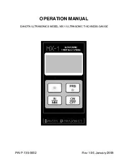
DAKOTA ULTRASONICS MODEL MX1 ULTRASONIC THICKNESS GAUGE PN P 139 0002 Rev 1 9 0 January 2008 Copyright ID: 450061

DAKOTA ULTRASONICS MODEL MX-1

Share:

Link:

Embed:

Download Presentation from below link

Download Pdf The PPT/PDF document "OPERATION MANUAL" is the property of its rightful owner. Permission is granted to download and print the materials on this web site for personal, non-commercial use only, and to display it on your personal computer provided you do not modify the materials and that you retain all copyright notices contained in the materials. By downloading content from our website, you accept the terms of this agreement.


Presentation Transcript

OPERATION MANUAL DAKOTA ULTRASONICS MODEL MX-1 ULTRASONIC THICKNESS GAUGE P/N P - 139 - 0002 Rev 1. 9 0 , January 2008 Copyright ã 2008 Dakota Ultrasonics. All rights reserved. No part of this publication may be reproduced, translated into another language, stored in a retrieval system, or transmitted in any form or by any means; electronic, mechanical, photocopying, recording, or otherwise, without the prior written consent of Dakota Ultrasonics. Every precaution has been taken in the preparation of this publication. Dakota Ultrasonics assumes no responsibility for errors or omissions. Neither is any liability assumed for damages resulting from the use of information contained herein. Any brand or product names mentioned herein are used for identification purposes only, and are trademarks or registered trademarks of their respective holders. 1500 Green Hills Road, #107 Scotts Valley, CA 95066 USA Tel (831) 431-9722 Fax (831) 431- www.dakotaultrasonics.com MX1 Ultrasonic Thickness Gauge CONTENTS I O THE K THE D THE T MAKING M CONDITION AND PREPARATION OF S PROBE Z C PROGRAMMING THE MXS SOUND V TRANSDUCER S APPENDIX A: PRODUCT S APPENDIX B: APPLICATION N APPENDIX C: SOUND VELOCITIES OF COMMON M WARRANTY I 1 3 3 5 7 8 10 11 12 12 14 17 19 23 25 DISCLAIMER Inherent in ultrasonic thickness measurement is the possibility that the instrument will use the second rather than the first echo from the back surface of the material being measured. This may result in a thickness reading that is TWICE what it should be. Responsibility for proper use of the instrument and recognition of this phenomenon rests solely with the user of the instrument. Dakota Ultrasonics blank page MX1 Ultrasonic Thickness Gauge 1 INTRODUCTION The Dakota Ultrasonics model MX is a precision Ultrasonic Micrometer. Based on the same operating principles as SONAR, the MX is capable of measuring the thickness of various materials with accuracy as high as ± 0.001 inches, or ± 0.01 millimeters. The principle advantage of ultrasonic measurement over traditional methods is that ultrasonic measurements can be performed with access to only one side of the material being measured. This manual is presented in three sections. The first section covers operation of the MX, and explains the keypad controls and display. The second section provides guidelines in selecting a transducer for a specific application. The last section provides application notes and a table of sound velocity values for various materials. Dakota Ultrasonics maintains a customer support resource in order to assist users with questions or difficulties not covered in this manual. Customer support may be reached at any of the following: · Dakota Ultrasonics, 1500 Green Hills Road, #107 Scotts Valley, CA 95066 USA · Telephone: (831) 431 · Facsimile: (831) 431 · www.dakotaultrasonics.com Dakota Ultrasonics 2 blank page MX1 Ultrasonic Thickness Gauge 3 OPERATION The MX interacts with the operator through the membrane keypad and the LCD display. The functions of the various keys on the keypad are detailed below, followed by an explanation of the display and its various symbols. This key is used to turn the MX on and off. When the gauge is turned ON, it will first perform a brief display test by illuminating all of the segments in the display. After one second, the gauge will display the internal software version number. After displaying the version number, the display will show "0.000" (or "0.00" if using metric units), indicating the gauge is ready for use. The MX is turned OFF by pressing the ON/OFF key. The gauge has a special memory that retains all of its settings even when the power is off. The gauge also features an auto-powerdown mode designed to conserve battery life. If the gauge is idle for 5 minutes, it will turn itself off. Dakota Ultrasonics 4 The PRB key is used to "zero" the MX in much the same way that a mechanical micrometer is zeroed. If the gauge is not zeroed correctly, all of the measurements that the gauge makes may be in error by some fixed value. Refer to page 11 for an explanation of this important procedure. The IN/MM key is used to switch back and forth between English and Metric units. This key may be used at any time, whether the gauge is displaying a thickness (IN or MM) or a velocity value (IN/ or M/s The BACKLIGHT key switches the display backlight between three available settings. OFF will be displayed when the backlight is switched off. AUTO will be displayed when the backlight is set to automatic mode, and ON will be displayed when the backlight is set to stay on. In the AUTO setting, the backlight will illuminate when the MX is actually making a measurement. MX1 Ultrasonic Thickness Gauge 5 The Display The numeric portion of the display consists of 4 complete digits preceded by a leading "1", and is used to display numeric values, as well as occasional simple words, to indicate the status of various settings. When the MX is displaying thickness measurements, the display will hold the last value measured, until a new measurement is made. Additionally, when the battery voltage is low, the entire display will begin to flash. When this occurs, the batteries should be replaced. These eight vertical bars form the Stability Indicator. When the MX is idle, only the left-most bar and the underline will be on. When the gauge is making a measurement, six or seven of the bars should be on. If fewer than five bars are on, the MX is having difficulty achieving a stable measurement, and the thickness value displayed will most likely be erroneous. Dakota Ultrasonics 6 When the IN symbol is on, the MX is displaying a thickness value in inches. The maximum thickness that can be displayed is 19.999 inches. When the MM symbol is on, the MX is displaying a thickness value in millimeters. If the displayed thickness exceeds 199.99 millimeters, the decimal point will shift automatically to the right, allowing values up to 1999.9 millimeters to be displayed. When the IN symbol is on, in conjunction with the / symbol, the MX is displaying a sound-velocity value in inches When the M symbol is on, in conjunction with the /s symbol, the MX is displaying a sound-velocity value in meters MX1 Ultrasonic Thickness Gauge 7 The Transducer The transducer is the "business end" of the M. It transmits and receives the ultrasonic sound waves which the MX uses to calculate the thickness of the material being measured. The transducer connects to the MX via the attached cable, and two coaxial connectors. When using transducers manufactured by Dakota Ultrasonics, the orientation of the dual coaxial connectors is not critical: either plug may be fitted to either socket in the MX The transducer must be used correctly in order for the MX to produce accurate, reliable measurements. Below is a short description of the transducer, followed by instructions for its use. This is a bottom view of a typical transducer. The two semicircles of the wearface are visible, as is the barrier separating them. One of the semicircles is responsible for conducting ultrasonic sound into the material being measured, and the other semicircle is responsible for conducting the echoed sound back into the transducer. When the transducer is placed Dakota Ultrasonics 8 against the material being measured, it is the area directly beneath the center of the wearface that is being measured. This is a top view of a typical transducer. Press against the top with the thumb or index finger to hold the transducer in place. Moderate pressure is sufficient, as it is only necessary to keep the transducer stationary, and the wearface seated flat against the surface of the material being measured. Making Measurements In order for the transducer to do its job, there must be no air gaps between the wear-face and the surface of the material being measured. This is accomplished with the use of a "coupling" fluid, commonly called "couplant". This fluid serves to "couple", or transmit, the ultrasonic sound waves from the transducer, into the material, and back again. Before attempting to make a measurement, a small amount of couplant should be applied to the surface of the material being measured. Typically, a single droplet of couplant is sufficient. After applying couplant, press the transducer (wearface down) firmly against the area to be measured. The Stability Indicator should have six or seven bars darkened, and a number should appear in the display. If the MX has been properly "zeroed" (see page 11) and set to the correct MX1 Ultrasonic Thickness Gauge 9 sound velocity (see page 12), the number in the display will indicate the actual thickness of the material directly beneath the transducer. If the Stability Indicator has fewer than five bars darkened, or the numbers on the display seem erratic, first check to make sure that there is an adequate film of couplant beneath the transducer, and that the transducer is seated flat against the material. If the condition persists, it may be necessary to select a different transducer (size or frequency) for the material being measured. See page 14 for information on transducer selection. While the transducer is in contact with the material being measured, the MX will perform four measurements every second, updating its display as it does so. When the transducer is removed from the surface, the display will hold the last measurement made. IMPORTANT Occasionally, a small film of couplant will be drawn out between the transducer and the surface as the transducer is removed. When this happens, the MX may perform a measurement through this couplant film, resulting in a measurement that is larger or smaller than it should be. This phenomenon is obvious when one thickness value is observed while the transducer is in place, and another value is observed after the transducer is removed. Dakota Ultrasonics 10 Condition and Preparation of Surfaces In any ultrasonic measurement scenario, the shape and roughness of the test surface are of paramount importance. Rough, uneven surfaces may limit the penetration of ultrasound through the material, and result in unstable, and therefore unreliable, measurements. The surface being measured should be clean, and free of any small particulate matter, rust, or scale. The presence of such obstructions will prevent the transducer from seating properly against the surface. Often, a wire brush or scraper will be helpful in cleaning surfaces. In more extreme cases, rotary sanders or grinding wheels may be used, though care must be taken to prevent surface gouging, which will inhibit proper transducer coupling. Extremely rough surfaces, such as the pebble-like finish of some cast irons, will prove most difficult to measure. These kinds of surfaces act on the sound beam like frosted glass on light, the beam becomes diffused and scattered in all directions. In addition to posing obstacles to measurement, rough surfaces contribute to excessive wear of the transducer, particularly in situations where the transducer is "scrubbed" along the surface. Transducers should be inspected on a regular basis, for signs of uneven wear of the wearface. If the wearface is worn on one side more than another, the sound beam penetrating the test material may no longer be perpendicular to the material surface. In this case, it will be difficult to exactly locate tiny irregularities in the material being measured, as the focus of the soundbeam no longer lies directly beneath the transducer. MX1 Ultrasonic Thickness Gauge 11 Probe Zero Setting the Zero Point of the MX is important for the same reason that setting the zero on a mechanical micrometer is important. If the gauge is not "zeroed" correctly, all of the measurements the gauge makes will be in error by some fixed number. When the MX is "zeroed", this fixed error value is measured and automatically corrected for in all subsequent measurements. The MX may be "zeroed" by performing the following procedure: Performing a Probe- 1) Make sure the MX is on. 2) Plug the transducer into the MX. Make sure that the connectors are fully engaged. Check that the wearface of the transducer is clean and free of any debris. 3) On the top of the MX, above the display, is the metal probe-disc. Apply a single droplet of ultrasonic couplant to the face of this disc. 4) Press the transducer against the probe-disc, making sure that the transducer sits flat against the surface of the probe-disc. The display should show some thickness value, and the Stability Indicator should have nearly all its bars illuminated. 5) While the transducer is firmly coupled to the probe-disc, press the PRB key on the keypad. The MX will display "Prb0" while it is calculating its zero point. 6) Remove the transducer from the probe- Dakota Ultrasonics 12 At this point, the MX has successfully calculated it's internal error factor, and will compensate for this value in any subsequent measurements. When performing a "probe-zero", the MX will always use the sound-velocity value of the built-in probe-disc, even if some other velocity value has been entered for making actual measurements. Though the MX will remember the last "probe-zero" performed, it is generally a good idea to perform a "probe-zero" whenever the gauge is turned on, as well as any time a different transducer is used. This will ensure that the instrument is always correctly zeroed. Calibration In order for the MX to make accurate measurements, it must be set to the correct sound-velocity for the material being measured. Different types of material have different inherent sound-velocities. For example, the velocity of sound through steel is about 0.233 inches-microsecond, versus that of aluminum, which is about 0.248 inches-microsecond. If the gauge is not set to the correct sound-velocity, all of the measurements the gauge makes will be erroneous by some fixed percentage. Programming the Sound Velocity Since the MX is a fixed velocity gauge, the correct sound velocity for the material being measured must be programmed into the gauge via the serial port on the bottom of the unit. Approximate sound velocities for common materials can be found in appendix C. MX1 Ultrasonic Thickness Gauge 13 Programming the MX- 1) Connect the serial cable (Part No. N-0010) to a COM port on a computer and to the RS232 connector located on the bottom of the MX. Remove and replace the rubber plug before and after programming. 2) Assuming that DakView2 PC software is installed and running, select the MX icon from the DakView2 gauge selector icons. A window will appear with the title “MX1 Velocity Upload Utilty”. 3) Under the Preset Velocity heading are two options. The first option is a test box with a velocity number displayed. The text box is editable. To change the velocity, click in the text field and type in the appropriate velocity number. The second option is a list box with a material type displayed. To change the material type, click the down arrow located to the right of the list box. Use the arrows or slider bar to scroll through the available material types. Click on a material to select it. 4) To select the units (english or metric), click on the radio button located to the left of the units title. A black dot will appear in the button when selected. 5) Click on the Program Gauge button located in the top right of the window. A pop up window will be display with the following message “Turn on gauge power”. Press the ON/OFF button on the MX to download the velocity. The MX will display the new velocity. Dakota Ultrasonics 14 TRANSDUCER SELECTION The MX is inherently capable of performing measurements on a wide range of materials, from various metals to glass and plastics. Different types of material, however, will require the use of different transducers. Choosing the correct transducer for a job is critical to being able to easily perform accurate and reliable measurements. The following paragraphs highlight the important properties of transducers, which should be considered when selecting a transducer for a specific job. Generally speaking, the best transducer for a job is one that sends sufficient ultrasonic energy into the material being measured such that a strong, stable echo is received by the MX. Several factors affect the strength of ultrasound as it travels. These are outlined below: · Initial Signal Strength The stronger a signal is to begin with, the stronger its return echo will be. Initial signal strength is largely a factor of the size of the ultrasound emitter in the transducer. A large emitting area will send more energy into the material being measured than a small emitting area. Thus, a so-called "1/2-inch" transducer will emit a stronger signal than a "1/4-inch" transducer. · Absorption and Scattering As ultrasound travels through any material, it is partly absorbed. If the material through which it travels has any grain structure, the sound waves will also experience scattering. Both of these effects reduce the MX1 Ultrasonic Thickness Gauge 15 strength of the waves, and thus, the MX's ability to detect the returning echo. Higher frequency ultrasound is absorbed and scattered more than ultrasound of a lower frequency. While it may seem that using a lower frequency transducer might be better in every instance, low frequencies are less directional than high frequencies. Thus, a higher frequency transducer would be a better choice for detecting the exact location of small pits or flaws in the material being measured. · Geometry of the Transducer The physical constraints of the measuring environment sometimes determine a transducer's suitability for a given job. Some transducers may simply be too large to be used in tightly confined areas. Also, the surface area available for contacting with the transducer may be limited, requiring the use of a transducer with a small wearface. Measuring on a curved surface, such as an engine cylinder wall, may require the use of a transducer with a matching curved wearface. · Temperature of the Material When it is necessary to measure on surfaces that are exceedingly hot, high temperature transducers must be used. These transducers are built using special materials and techniques that allow them to withstand high temperatures without damage. Additionally, care must be taken when performing a "Probe-Zero" or "Calibration to Known Thickness" with a high temperature transducer. See Appendix B for more information on measuring materials with a high temperature transducer. Dakota Ultrasonics 16 Selection of the proper transducer is often a matter of tradeoffs between various characteristics. It may be necessary to experiment with a variety of transducers in order to find one that works well for a given job. Dakota Ultrasonics can provide assistance in choosing a transducer, and offers a broad selection of transducers for evaluation in specialized applications. MX1 Ultrasonic Thickness Gauge 17 APPENDIX A Product Specifications Physical Weight: 10 ounces Size: 2.5W x 4.75H x 1.25D inches (63.5W x 120.7H x 31.8D mm). Operating Temperature: -20 to 120 °F (-20 to 50 ° Case: Extruded aluminum body / nickel plated aluminum end caps. Keypad Sealed membrane, resistant to water and petroleum products. Power Source Two “AA” size, 1.5 volt alkaline or 1.2 volt NiCad cells. 200 hours typical operating time on alkaline, 120 hours on NiCad. Display LiquidDisplay, 4.5 digits, 0.500 inch high numerals. LED backlight. Measuring Range: 0.025 to 19.999 inches (0.63 to 500 millimeters) Resolution: 0.001 inch (0.01 millimeter) Accuracy: ±0.001 inch (0.01 millimeter), depends on material and conditions Sound Velocity Range: 0.0492 to 0.3930 in/ms (1250 to 10000m/s) Dakota Ultrasonics 18 blank page MX1 Ultrasonic Thickness Gauge 19 APPENDIX B Application Notes · Measuring pipe and tubing When measuring a piece of pipe to determine the thickness of the pipe wall, orientation of the transducers is important. If the diameter of the pipe is larger than approximately 4 inches, measurements should be made with the transducer oriented so that the gap in the wearface is perpendicular (at right angle) to the long axis of the pipe. For smaller pipe diameters, two measurements should be performed, one with the wearface gap perpendicular, another with the gap parallel to the long axis of the pipe. The smaller of the two displayed values should then be taken as the thickness at that point. Perpendicular Parallel · Measuring hot surfaces The velocity of sound through a substance is dependant upon its temperature. As materials heat up, the velocity of sound through them decreases. In most applications with surface temperatures less than about 200F (100°C), no special procedures must be observed. At temperatures Dakota Ultrasonics 20 above this point, the change in sound velocity of the material being measured starts to have a noticeable effect upon ultrasonic measurement. At such elevated temperatures, it is recommended that the user perform a calibration procedure (refer to page 11) on a sample piece of known thickness, which is at or near the temperature of the material to be measured. This will allow the MX to correctly calculate the velocity of sound through the hot material. When performing measurements on hot surfaces, it may also be necessary to use a specially constructed high-temperature transducer. These transducers are built using materials which can withstand high temperatures. Even so, it is recommended that the probe be left in contact with the surface for as short a time as needed to acquire a stable measurement. While the transducer is in contact with a hot surface, it will begin to heat up itself, and through thermal expansion and other effects, may begin to adversely affect the accuracy of measurements. · Measuring laminated materials Laminated materials are unique in that their density (and therefore soundvelocity) may vary considerably from one piece to another. Some laminated materials may even exhibit noticeable changes in sound-velocity across a single surface. The only way to reliably measure such materials is by performing a calibration procedure on a sample piece of known thickness. Ideally, this sample material should be a part of the same piece being measured, or at least from the same lamination batch. By calibrating to each test piece individually, the effects of variation of sound-velocity will be minimized. MX1 Ultrasonic Thickness Gauge 21 An additional important consideration when measuring laminates, is that any included air gaps or pockets will cause an early reflection of the ultrasound beam. This effect will be noticed as a sudden decrease in thickness in an otherwise regular surface. While this may impede accurate measurement of total material thickness, it does provide the user with positive indication of air gaps in the laminate. Dakota Ultrasonics 22 blank page MX1 Ultrasonic Thickness Gauge 23 APPENDIX C Sound Velocities of some Common Materials Materialsound velocity in/us m/s Aluminum 0.250 6350 Bismuth 4394 Cast Iron 4572 4674 Epoxy resin 2540 German silver0.187 lass, crown 5664 3251 5893 5791 2591 3962 2337 2388 Quartz glass0.222 Rubber, vulcanized 2311 3607 Steel, common0.233 Steel, stainless 5664 1422 6096 4216 Dakota Ultrasonics 24 blank page MX1 Ultrasonic Thickness Gauge 25 WARRANTY INFORMATION · Warranty Statement · Dakota Ultrasonics warrants the MX-1 against defects in materials and workmanship for a period of five years from receipt by the end user. Additionally, Dakota Ultrasonics warrants transducers and accessories against such defects for a period of 90 days from receipt by the end user. If Dakota Ultrasonics receives notice of such defects during the warranty period, Dakota Ultrasonics will either, at its option, repair or replace products that prove to be defective. Should Dakota Ultrasonics be unable to repair or replace the product within a reasonable amount of time, the customer's alternative exclusive remedy shall be refund of the purchase price upon return of the product. · Exclusions · The above warranty shall not apply to defects resulting from: improper or inadequate maintenance by the customer; unauthorized modification or misuse; or operation outside the environmental specifications for the product. Dakota Ultrasonics makes no other warranty, either express or implied, with respect to this product. Dakota Ultrasonics specifically disclaims any implied warranties of merchantability or fitness for a particular purpose. Some states or provinces do not allow limitations on the duration of an implied warranty, so the above limitation or exclusion may not apply to you. However, any implied warranty of merchantability or fitness is limited to the five-year duration of this written warranty. This warranty gives you specific legal rights, and you may also have other rights which may vary from state to state or province to province. · Obtaining Service During Warranty Period · If your hardware should fail during the warranty period, contact Dakota Ultrasonics and arrange for servicing of the product. Retain proof of purchase in order to obtain warranty service. For products that require servicing, Dakota Ultrasonics may use one of the following methods: - Repair the product - Replace the product with a re-manufactured unit - Replace the product with a product of equal or greater performance - Refund the purchase price. · After the Warranty Period · If your hardware should fail after the warranty period, contact Dakota Ultrasonics for details of the services available, and to arrange for non-warranty service. Dakota Ultrasonics 26 blank page MATERIAL SAFETY DATA SHEETN/A = not applicable or not available(To comply with 29 CFR 1910.1200)SECTION 1 – PRODUCT IDENTIFICATIONProduct Name: SOUNDSAFEGeneric Name: Ultrasonic CouplantManufacturer: Sonotech, Inc. 774 Marine Dr., Bellingham, WA 98225 (360) 671-9121NFPA Hazardous MaterialsIdentification System (est) SECTION 2 – HAZARDOUS INGREDIENTSThis material does not contain any ingredients havingknown health hazards in concentrations greater than 1%.This material does not contain any known or suspectedcarcinogens.SECTION 3 – PHYSICAL DATA(�Boiling Point: 220°: 7.35 – 7.9Freezing Point: °Acoustic Imp.: 1.726x10⁶Vapor Pressure: N/AVapor Density: N/AEvaporation Rate: N/A Specific Gravity: 1.02Solubility in Water: completeAppearance and Odor: water white, opaque gel; bland odorSECTION 4 – FIRE AND EXPLOSIONHAZARD DATAFlash Point: noneUpper Exposure Limit: noneLower Exposure Limit: noneSpecial Fire Fighting Procedures: N/AExtinguishing media: N/AUnusual Fire and Explosion Hazards: noneSECTION 5 – REACTIVITY DATAStability: StableConditions to Avoid: noneIncompatibility (Materials to Avoid): none knownHazardous Polymerization: will not occurHazardous Decomposition or Byproducts: none knownSECTION 6 – HEALTH HAZARD AND FIRST AID DATARoutes of Entry: Skin: not likelyIngestion: not normallyEyes: not normallyInhalation: noEffects of Overexposure:: May cause temporary eye irritationChronic: none expectedFirst Aid Procedures: Skin: Remove with water if desired.Eyes: Flush with water for 15 minutes.Ingestion: For large quantities, induce vomiting andcall a physician.Inhalation: N/ASECTION 7 – STORAGE AND HANDLINGINFORMATIONPrecautions to be taken in handling and storage: Store between 20°F and 120°F. Spills are slippery and shouldbe cleaned up immediately.Steps to be taken in case material is released or spilled: Pick up excess for disposal. Clean with water.Waste disposal method: Dispose of in accordance with federal, state, and local regulations.SECTION 8 – CONTROL MEASURESRespiratory Protection: not requiredVentilation: not requiredProtective Gloves: on individuals demonstrating sensitivity to SOUNDSAFEÒEye Protection: as required by working conditionsOther Protective Equipment: not required1 contains only food grade and cosmetic grade ingredients.Toll Free: 1-800-458-4254SONOTECH, INC.774 Marine Dr., Bellingham, WA 98225Telephone: (360) 671-9121Fax: (360) 671-9024