/
Page:Page:Checks and Adjustments Before Stepping11 Page:Page:Checks and Adjustments Before Stepping11

Page:Page:Checks and Adjustments Before Stepping11 - PDF document

debby-jeon
debby-jeon . @debby-jeon
Follow
424 views
Uploaded On 2015-07-26

Page:Page:Checks and Adjustments Before Stepping11 - PPT Presentation

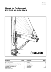
Manual for Furling mastTYPE RB Mk IIRC Mk II 595063E20140812 Product descriptionThe furling geer been developed from experience gained from FURLEX foresail rollerreefing and is The unique desig ID: 93519

Manual for Furling mastTYPE

Share:

Link:

Embed:

Download Presentation from below link

Download Pdf The PPT/PDF document "Page:Page:Checks and Adjustments Before ..." is the property of its rightful owner. Permission is granted to download and print the materials on this web site for personal, non-commercial use only, and to display it on your personal computer provided you do not modify the materials and that you retain all copyright notices contained in the materials. By downloading content from our website, you accept the terms of this agreement.


Presentation Transcript

Page:Page:Checks and Adjustments Before Stepping11 Manual for Furling mastTYPE RB Mk II/RC Mk II 595-063-E2014-08-12 Product descriptionThe furling geer been developed from experience gained from FURLEX foresail roller-reefing, and is The unique design of the halyard swivel bearing distributes the load over the whole ballrace to give The entire reefing mechanism can be easily removed from the mast for service. Stainless steel thread inserts The mast extrusion has an additional luff groove for a storm trysail or spare main. In an emergency even a foresail with rope luff could be hoisted.This Instruction Manual has been compiled to give you information on the in-mast reefing system. Study it and follow the instructions carefully, and we guarantee you many years of pleasurable use from your Seldén Follow the relevant rigging instructions in our booklet ”HINTS AND ADVICE” for tuning the rig. Asymmetric luff extrusion giving reduced initial resistance to reefing due to easier bending of the luff. Sail Compartment Fig. 2:1 Cable Conduits 3 Extra Sheave box for furling jib halyardTop swivelHalyard swivelTopping lift (1:2)In-mast furling gear.Reefing WinchTurning BlocksAccess to Sail Feeder and Halyard SwivelAccess to Tack Hook and Tensioning ScrewAccess for greasingOpening for in-mast stowage of halyard tail 4 Remove the Access covers.Luff extrusion adjustmentChecking luff extrusion tension prior to stepping the mastThe luff extrusion is correctly tensioned before leaving the factory, but tension can be re-checked before mast in the following manner.neccesary see points 1-5 below.If adjustment has to be made after the mast has been stepped, then the luff extrusion should be so tensioned that it DO NOT OVER-TENSION! A luff extrusion that is over-tensioned will require increased furling effort. Locking TubeLocking Retaining ScrewTensioning Screw Push the Locking Tube upwards above theSail Feeder. Lock the Tube in this position bylower end of the Sail Feeder.The screwdriver will also stop the luff Sectionoil. Turn the Ree�ng winch using the winch handleuntil the luff is correctly tensioned.Adjust so that the Locking Tube �ts over thelower part off the Luff Section. Lower theLocking Tube to locking position. Replacethe Lock Retaining Screw.Locking Tube. 6 Reefing and unreefing is accomplished with a reefing line and an outhaul operated either from the cockpit or by working at Operating at the mast is recommended with type RC. This is due to the friction in the control lines system from mast to cockpit on a large yacht.is to be operated from the cockpit then a reefing line in the form of an endless loop in combination with a self-tailing winch is recommended. The endless loop must have surplus length to allow it to be easily removed from the winch. The tail-end of the loop must also be belayed on a cleat or Clam-cleat.A rope-stopper can also be used, but it should be of a type that can be dismantled so that a pre-spliced loop can be fed into it. A self-tailing winch is also recommended for the clew outhaul line. A rope-stopper that permits controlled paying out, such as Topping lift & kicking strapWe recommend that the topping lift and kicking strap also be handled from the cockpit. These lines are best belayed with rope-stoppers. The topping lift should be ended with a figure-of-eight stopper knot to prevent it inadvertently running out. This stopper-knot should be placed where the rope exits from the boom, and in such a position that it will prevent the boom from dropping below its lowest necessary level. (NOTE. This is not necessary if a rod type kicking strap is used).NOTE! Because the endless line is led through the same turning block in both directions excess friction can be Layout 1Layout 2. Turning BlocksTurning BlocksRope-Stoppers Topping LiftTopping LiftEndless Reefing Endless Reefing (CL 238 with spring gate)(CL 238 with spring gate) Alternative Clew Outhaul Arrangement. When reefing from the cockpit the Reefing Winch must be set to ”free”. The mast Turning Block has removable sheaves and a slot to allow the endless loop to be fitted even when Note. This type of turning block is designed for reefing system control lines exclusively!809-01, three sheaves; or 538-810-01, 4 sheaves). A pre-spliced endless loop can be threaded through them.If fittings from other suppliers are used they should have similar features to the foregoing. Fittings with Free both sides of the endless loop from the winch and Clam-Cleat. It will then slide on the Reefing Winch. FurlingThe leech should be kept fairly tight when reefing or furling. Adjust the topping lift to achieve this, and the sail will form a good tight roll around the luff extrusion. Keep slight tension on the outhaul while doing this. This applies especially when the wind is abaft the beam or in light air.Always lock the Reefing Winch when leaving the boat.ReefingCarefully slacken off the outhaul line.Whilst continuing to ease off the outhaul, roll in the desired amount of sail.When working at the mast: activate the lock on the Reefing Winch (-IN’) before reefing the sail.When the sail. When operating from the cockpit: make both ”sides” of the reefing line fast to prevent slip on the Reefing Winch. Finally, tension the outhaul. WARNING! Never leave the handle in the Reefing Winch!It will rotate very rapidly when the sail is unfurled. Fig. 7:1 Fig. 7:2 8 Check that the Tack and Head of the sail are made as illustrated on Page 10. An incorrectly made tack can cause wrinkles in the sail and make smooth furling difficult. Join the Tack to the tack hook. Vibration can occur in any aluminium mast of normal design. With wind coming from approximately abeam 6 cycles per second. As an optional item an ”anti-vibration strip” is available for hoisting in the integral sail groove at the aft face of the mast to prevent vibration starting. It will also reduce wind noise. For further information, contact Seldén Mast AB. Port Fig. 9:1 StarboardCheck that the sail is correctly furled on the STARBOARD SIDE of the luff extrusion. (See Fig. Furl and unfurl the sail a couple of times to ensure that the system works as it should, and to familiarise The area aft of the mast must be free from halyards etc. or these can be caught by the sail during the furling Note. Turn the reefing winch clockwise for correct Attach the clew to the Outhaul Car.Hoist the mainsail whilst simultaneously ensuring that it is feeding correctly into the luff extrusion. Set the halyard and cleat it with the rope stopper. The halyard tail can be stowed in the mast by feeding it through the hole just below the halyard winch.Furl the sail until the clew is exposed. The luff extru-sion is asymmetrical to facilitate rolling in one direc-tion, and the sail should always be rolled onto the star-board side of the luff extrusion. The Ree�ng Winch should be turned clockwise. See Fig. 9:1. 10 The luff extrusion is asymmetrically shaped to help overcome initial resistance when starting to furl. To improvesail shape when reefed and to reduce draft. ”Luff Foam” may be used along the luff. The foam should not beplaced closer than 50 mm (2”) from the font edge of the luff as it will then increase initail reefing resistance. Tofurther reduce resistance use as ligth cloth as possible in the luff tape.We recommend maxium 8 mm (5/16”) diameter luff-rope/luff-tape (maximum 7 mm (9/32”) hard line).Luff groove dimensions are shown in fig. 10:2.Head and tack tapes should be of soft quality which can foald easily. Do not use metal eyelets on them. Fig. 10:2* Boom Brackets No. 508-151 och 508-153.Fig. 10:1Measurement to centreof Boom Bracket (marked) Max Sail Space The spare Mainsail, which should be carried on board every yacht, can be hoisted in the intergrated sail We recommend Aquabatten AO32 or Rutgerson 101 sail-slides for this sail.A foresail made for a luff extrusion, for a Furlex for example, can also be used in this sail groove. Boom Toggle Size* 200/117 11 Cables for forward- facing electrical installations are held in place with an ”ETHAFOAM” pad to eliminate Drill the exit hole for the cable through the other corner and forward of the cable. Use great caution Carefully burr the hole to eliminate any sharp edges that could cause chafe. Some tape around the cable All in-mast furling mast extrusions have one or more cable conduits. These run uninterrupted to the mast heel even on keel stepped masts. A messenger is threaded through all empty conduits at the factory to facilitate cable drawing. A new messenger should be drawn through a conduit at the same time as a cable is drawn through. This will facilitate the running of additional cables. If an existing cable should prevent a new one being run, it should be extracted after first having attached a new messenger to it to take its place in the conduit. That messenger can then be used to pull two or more cables through the conduit simultaneously. Cables are led into a conduit at the masthead through a hole in the side of the mast extrusion. Cables should be over-length. The head box can then later be removed without the need to disconnect electric installations. Cable Fig. 11:1 12 Maintenance of the in-mast furling mast Periodic MaintenanceMaintenance should be undertaken at least once a year. All bearings should be greased with GREASE (Part No. When greasing bearings and gears, do not over-grease. A thin coating of evenly applied grease is sufficient.TOP SWIVEL: marked ”GREASE” where the grease should be injected. Access through the HALYARD SWIVEL: in the ring. This is best done through the upper IN-MAST FURLING MAST GEAR.Remove the upper, oval plastic plug Complete ServiceIt is a good idea after some years use to dismantle the gear for thorough cleaning and re-greasing. The in-mast furling mast is built so that servicing will be easy even after protracted use. Stainless steel thread inserts for all screw Removal of the in-mast furling mast gear from the mastRelieve tension on the Luff Extrusion by slackening the Tensioning Screw. (The Tensioning Screw is descri. Detach the Luff Extrusion from the furling Gear through the Grease Hole. are removed. Remove the furling Gear from the mast by undoing the eight holding screws and taking it away from the mast. . The box can then be lifted off. Detach the Top Swivel The luff section and the Halyard Swivel can now be pulled out of the mast. 11 13 Fig. 13:1 14 All dismantling should be done on a clean unbroken surface. The various ball bearing units contain many small parts that fall apart when dismantling. Lay the dismantled parts out in an orderly manner. Dismantling the in-mast furling mast gear:Tools required: – Hammer – Allen key, 6 mm.– Screwdriver, small from the large bevel gear. up and out from the furling gear.Take care of the balls and ballraces which will fall from the small bevel gear. Draw the gear and ball bearings off the shaft. Take Undo the four screw holding the Reefing Winch, and remove the winch from the holding bracket. Remove loose components from the reverse side of the winch, and remove the locking ring from the shaft. The winch can then be dismantled.Clean the ball bearings, races, gears and winch Reassemble all components in the reverse order. The winch must be greased before reassembly. A layer of grease in the cupped half of a ballrace will hold the balls in place during assembly. Grease the Take care of ball bearings and races, which Fig 14.1 15 Tools required: and the four screws in Turn item off together with one ball bearing. Then lift off Reassemble the components in the reverse order. A layer of grease in the cupped half of a ball-race will hold the balls in place during assembly. NOTE. Ball bearings may fall apart. Take care not to Fig. 15:1 540-107or540-209 The Sail must always be rolled to the starboard side of the luff extrusion. Turn the reefing winch clock Lock the reefing winch at the mast when reefing in heavy weather.The Topping lift should have a stopper-knot to prevent the boom from dropping into the cockpit. Seldén Mast AB, Sweden Tel +46 (0)31 69 69 00Fax +46 (0)31 29 71 37 e-mail info@seldenmast.com Seldén Mast Limited, UK Tel +44 (0) 1329 504000Fax +44 (0) 1329 504049 Seldén Mast Inc., USA Tel +1 843-760-6278 Fax +1 843-760-1220 Seldén Mast A/S, DK Tel +45 39 18 44 00 Fax +45 39 27 17 00 e-mail info@seldenmast.dk Seldén Mid Europe B.V., NLTel +31 (0) 111-698 120Fax +31 (0) 111-698 130Tel +33 (0) 251 362 110www.seldenmast.comDINGHIESKEELBOATSYACHTS The Seldén Group is the world’s leading manubon and aluminium for dinghies, keelboats and yachts. The Group consists of Seldén Mast AB in Sweden, Seldén Mast A/S in Denmark, Seldén Mast Ltd in the UK, Seldén Mid Europe B.V. in the Netherlands, Seldén Mast Inc in the USA and Seldén Mast in France. Our well known brands are Seldén and Furlex. The worldwide success of Furlex has enabled us to build a network of over 750 authorised dealers covering the world’s marine markets. So wherever you sail, you can be sure of fast access to our service, spare parts and know-how.