/
MK15 User Manual MK15 User Manual

MK15 User Manual - PDF document

desha
desha . @desha
Follow
358 views
Uploaded On 2021-08-08

MK15 User Manual - PPT Presentation

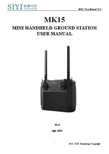
V1012021SIYI Technology Copyright MK15MINI HANDHELDGROUNDSTATIONUSER MANUALV10Apr2021MK15 User ManualV1022021SIYI Technology Copyright Thank you for purchasing SLL Technologys productaY15 is a 15kilo ID: 859912

siyi mk15 manual transmitter mk15 siyi transmitter manual user reserved nology tech receiver product blinks channel red system green

Share:

Link:

Embed:

Download Presentation from below link

Download Pdf The PPT/PDF document "MK15 User Manual" is the property of its rightful owner. Permission is granted to download and print the materials on this web site for personal, non-commercial use only, and to display it on your personal computer provided you do not modify the materials and that you retain all copyright notices contained in the materials. By downloading content from our website, you accept the terms of this agreement.


Presentation Transcript

1 MK15 User Manual V1. 0 1 20 21 S
MK15 User Manual V1. 0 1 20 21 SIYI Technology Copyright MK15 MINI HANDHELD GROUND STATION USER MANUAL V1. 0 A p r 20 2 1 MK15 User Manual V1. 0 2 20 21 SIYI Technology Copyright Thank you for purchasing SL⚫L Technology’s product. aY15 is a 15 - kilometer range Android smart controller with dual 1080p CtV, based on the full high - definition image transmission technology, which is completely and independently developed by SL⚫L Technology. The system is deeply optimized and integrated with vualcomm 8 - core /tU platform. aY15’s abundant features and powerful performance m ake it a commonly applied device of reliable image transmission and solid control on agriculture drones, commercial drones, unmanned vehicles , and boats, and robotics. To maintain a safe and orderly public space and to ensure you a good using experience o f aY15 mini handheld ground stat

2 ion , please read this manual carefully.
ion , please read this manual carefully. Lf you have any issue using the product, please consult the manual or check online pages of aY15 on SL⚫L Technology’s official website (http://www.siyi.biz). ⚫ou can also send an email to SL⚫L official A/S center ( support@siyi.biz ). MK15 User Manual V1. 0 3 20 21 SIYI Technology Copyright SIYI User Group - Facebook SIYI YouTube Channel ( https://www.youtube.com/channel/UC0vdyQDSRr3fiCffNKnYimA ) SIYI Official Aliexpress Store ( https://www.aliexpress.com/store/911142095?spm=a2g0o.sto re_home.1000001.11.22595727l31Low ) MK15 User Manual V1. 0 4 20 21 SIYI Technology Copyright CONTENT READ TIPS ................................ ................................ ................................ ................................ ............................ 1 Icon Definition ...........

3 ..................... ..................
..................... ................................ ................................ ................................ .................... 1 Flight Safety ................................ ................................ ................................ ................................ ....................... 1 Battery ................................ ................................ ................................ ................................ ................................ 3 Memory Card (SD/TF) ................................ ................................ ................................ ................................ ...... 3 How to Use SIM Card on MK15 ................................ ................................ ................................ ....................... 4 Precautions on Storage/Carrying/Recycling ................................ ................................ .....

4 ........................... ... 5 1
........................... ... 5 1 PRODUCT INTRODUCTION ................................ ................................ ................................ ........................... 6 1.1 Product Features ................................ ................................ ................................ ................................ ........ 6 1.2 Parts ................................ ................................ ................................ ................................ ............................. 9 1.2.1 At a Glance ................................ ................................ ................................ ................................ ........... 9 1.2.2 Button/Switch Types and Default Channel Definitions ................................ ................................ .. 11 1.2.3 Ports on MK15 Transmitter ................................ .........................

5 ....... ................................
....... ................................ ............... 12 1.2.3 Ports on MK15 Receiver ................................ ................................ ................................ ................... 14 1.3 Technical Specification ................................ ................................ ................................ ............................. 14 1. 4 Packing List ................................ ................................ ................................ ................................ ............... 17 1.5 MK15 Common Diagram ................................ ................................ ................................ .......................... 18 1.6 Indicator Definitions ................................ ................................ ................................ ................................ .. 19 1.6.1 Transmitter Indicator .............................

6 ... ................................ ...
... ................................ ................................ .......................... 20 1.6.2 Receiver Indicator ................................ ................................ ................................ .............................. 21 2 GET READY TO USE MK15 ................................ ................................ ................................ .......................... 22 2.1 Transmitter ................................ ................................ ................................ ................................ ................. 22 2.1.1 Power On/Off ................................ ................................ ................................ ................................ ...... 22 2.1.2 Charging ................................ ................................ ................................ ................................ ............. 23 2.1.3 Cha

7 rging ................................
rging ................................ ................................ ................................ ................................ ............. 23 2.2 How to Place MK15 Antennas ................................ ................................ ................................ ................. 24 3 SIYI TX APP ................................ ................................ ................................ ................................ ..................... 25 3.1 Channels ................................ ................................ ................................ ................................ .................... 26 3.1.1 End Point ................................ ................................ ................................ ................................ ............ 26 3.1.2 Middle Point ................................ ................................ .................

8 ............... ........................
............... ................................ ........ 27 3.1.3 Channe l Reverse ................................ ................................ ................................ ............................... 27 MK15 User Manual V1. 0 5 20 21 SIYI Technology Copyright 3.1.4 Channel Mapping ................................ ................................ ................................ ............................... 28 3.2 Datalink ................................ ................................ ................................ ................................ ...................... 29 3.2.1 Connection ................................ ................................ ................................ ................................ ......... 30 3.2.2 Flight Controller ................................ ................................ ................................ ................

9 ................ .. 31 3.2.3 Baud R
................ .. 31 3.2.3 Baud Rate ................................ ................................ ................................ ................................ ........... 31 3.3 System ................................ ................................ ................................ ................................ ....................... 32 3.3.1 Bind ................................ ................................ ................................ ................................ ..................... 33 3.3.2 Frequency Self - Adapting ................................ ................................ ................................ .................. 33 3.3.3 Th rottle Type ................................ ................................ ................................ ................................ ...... 34 3.3.4 Production Date ................................ ............

10 .................... ...................
.................... ................................ ................................ . 34 3.4 Status ................................ ................................ ................................ ................................ ......................... 34 3.5 Failsafe ................................ ................................ ................................ ................................ ....................... 35 3.6 Calibration ................................ ................................ ................................ ................................ .................. 38 3.7 Buttons ................................ ................................ ................................ ................................ ....................... 41 4 DATALINKS ................................ ................................ ................................ ..........................

11 ...... ...................... 43 4.1
...... ...................... 43 4.1 Communication with GCS through USB COM ................................ ................................ ...................... 43 4.2 Communication with GCS through Bluetooth ................................ ................................ ........................ 44 4.3 Solutions to Disconnection ................................ ................................ ................................ ....................... 44 5 IMAGE TRANSMISSION ................................ ................................ ................................ ................................ 46 5.1 Using SIYI IP Cameras ................................ ................................ ................................ ............................ 46 5.2 Using Third - Party IP Cameras / Pods ................................ ................................ ........................

12 ........ .... 46 5.3 Using HDMI Came
........ .... 46 5.3 Using HDMI Cameras / Pods ................................ ................................ ................................ .................. 47 5.4 Common IP Addresses ................................ ................................ ................................ ............................ 48 5.5 Solutions to No Image ................................ ................................ ................................ .............................. 48 6 ANDROID OS ................................ ................................ ................................ ................................ ................... 49 6.1 Download App ................................ ................................ ................................ ................................ ........... 49 6.2 Import and Install App ................................ ................................

13 ................................ .......
................................ .............................. 49 6.2.1 Through TF Card ................................ ................................ ................................ ............................... 49 6.3.2 Through USB Drive ................................ ................................ ................................ ........................... 50 7 Firmware Upgrade ................................ ................................ ................................ ................................ ........... 51 8 After - sale Service ................................ ................................ ................................ ................................ ............. 53 8.1 Repair Service ................................ ................................ ................................ ................................ ........... 53 MK15 User Manual V1. 0 6

14 20 21 SIYI Technology Copyright 8
20 21 SIYI Technology Copyright 8.2 Warranty ................................ ................................ ................................ ................................ .................... 54 8.2.1 7 - Day Return & Refund ................................ ................................ ................................ ..................... 54 8.2.2 15 - Day Replacement ................................ ................................ ................................ ......................... 55 8.2.3 1 - Year Warranty Repair ................................ ................................ ................................ .................... 57 MK15 User Manual V1. 0 1 20 2 1 SIYI Tech nology, All Right s Reserved READ TIPS Icon Definition Please pay more attention to content indicated with the following marks: DANGER Dangerous m anipulation probably leads to hum

15 an injuries. WARNING Warnings on m
an injuries. WARNING Warnings on m anipulation possibly le ads to human injuries. CAUTION Cautions on what m anipulation may lead to property loss. Prohibited Mandatory Mark Flight Safety MK15 Mini Handheld Ground Station is designed for professional application in specific industries, users who approaches to the device should have at least the basic knowledge to operate it . I rregular or irresponsible manipulations to the device may cause damage , property loss , or human injuries. U sers under 14 years’ old should follow an experienced trainer’s guid e . Disassembling or modification to the system is prohibited without permission from its manufacturer, SIYI Technology. To maintain a safe and orderly public space and to ensure you a good using experience of SIYI’s products, please read the prohibited and mandatory terms carefully . MK15 User Manual

16 V1. 0 2 20 2 1 SIYI Tech nology
V1. 0 2 20 2 1 SIYI Tech nology, All Right s Reserved Do not use any SIYI radio system to operate your aircraft /vehicle/model at places with intensive crowd ( a s quare , a park), or at places with many obstructions ( a street, a parking lot), or in fields with strong magnetic or interference ( an electricity plant, a radar station, railways) , or in any other fields where an irregular flight/operation may cause property loss or human injuri es. Do not hold or cover transmitter antenna or obstruct its transmission by any means in a flight or an operation . Never point your transmitter antenna’s upper ends straightly to your aircraft / vehicle while it is working, they are the weakest parts for transmission . Do not start your aircraft/vehicle/model when you are tired, dru nk, in sickness or any circumstances you are not feeling good .

17 Do not fly an aircraft/model when it i
Do not fly an aircraft/model when it is rainy, wind y or at night. Do not power off the transmitter w hile your aircraft ’s/vehicle’s/model’s engine s and motors are still working. Please always try to operate your aircraft /vehicle/model within sight range. Do not forget to check battery level of the transmitter and the receiver before starting your aircraft/vehicle/model . Always p ower off your aircraft /vehicle/model first , FT24 tr ansmitter the second . Before changing any settings on the transmitter, make sure your aircraft ’s/vehicle’s/model’s engine s are powered off and their motor wi res are off connection, in case of a sudden switch - on . MK15 User Manual V1. 0 3 20 2 1 SIYI Tech nology, All Right s Reserved When you start your aircraft/vehicle for the first time, make sure that the fail - safe settings in your transmitter

18 is activated. Always switch on the
is activated. Always switch on the transmitter first and hold the throttle joystick at its bottom position, then power on your aircraft /vehicle/model . Battery MK15 transmitter is equipped with a built - in and chargeable 1 020 0mAh Li - on battery and a 20W PD fast charger. Please do read the precautions before using and charging MK15 battery. Please power off MK15 transmitter before charging. The transmitter does not allow charging while it is working. Stop charging immediately if you f ound the charger damaged, broken or overheat . Stop charging immediately if there was a peculiar smell, smokes or leak s. In such cases you shall sent the transmitter back to your dealer for after - sales service . Do not charge the tr ansmitter when temperature is high, or battery temperature is over 60 ℃ . Memory Card (SD/TF) The me

19 mory card slot at bottom MK15 transmit
mory card slot at bottom MK15 transmitter supports reading from and writing into high - speed SD/TF card . Please mind the precautions below. MK15 User Manual V1. 0 4 20 2 1 SIYI Tech nology, All Right s Reserved Do not disassemble, bend, press, abandon or damage memory card by any means. Stop using the memory card if you find it soaked by water, oil or any other chemical liquid. CAUTION A memory card is also an electronic product, keep it away from static electricity. Keep the m emory card slot clean in case of blocking by sand or dirt. Keep the memory card in slot while you are downloadi ng or uploading data; taking out it mistakenly, hitting it or shatter ing it may cause damage or data loss. Keep the memory card away from places that a bab y or a kid may reach in case that it was swallowed mistakenly by the baby/kid . How to Use SIM Card on

20 MK15 MK15 supports 4G network, lik
MK15 MK15 supports 4G network, like a smartphone. You can put in a n SIM card into the transmitter to activate the function. B e fore putting in a n SIM card into MK15 transmitter, please check if it supports your local cellular network. Supported Format and Frequency Bands GSM/EGRPS 4 Frequency: EGSM900/DCS1800 WCDMA: B1/B8 LTE FDD : B1/B3/ B5/B7/ B8 MK15 User Manual V1. 0 5 20 2 1 SIYI Tech nology, All Right s Reserved LTE TDD: B34/B38/B39/B40/B41 E VDO/CDMA: BC0 CAUTION MK15 4G function is not certified. Please refer to your local radio laws or wireless regulations before activating 4G network. Precautions on Storage/Carrying/Recycling W hen your SIYI radio system is stand idle , or you are bringing it outdoors, or the system reached service life , then ple ase do read the precautions below. CAUTION Always place your MK15 transmitter at place

21 s where babies or kids do not reach .
s where babies or kids do not reach . DANGER MK15 transmitter should be placed as below : Not too hot (above 60 ℃ ) or too cold (under - 20 ℃ ) . Not under direct sunshine or too dusty or too wet. Not on an unstable holder which lacks solid supports or may cause vibration. Not nearby steam or other heat sources . MK15 User Manual V1. 0 6 20 2 1 SIYI Tech nology, All Right s Reserved 1 PRODUCT INTRODUCTION 1 .1 Product Features 15KM 1080P Image Transmission Once again SIYI made a breakthrough, applying this brand new and cutting edge high - definition image transmission technology on MK15 successfully. The technology comes with a smart ability to adapt its transmission to better frequency bands, which means it always goes to work on the band with least interference. With the standard omni directional antennas, MK15 system’s effective range can

22 reach up to 15 kilometers . With the lo
reach up to 15 kilometers . With the long - range antennas coming with MK15 enterprise combos, the range can be up to 30 kilometers with full HD image transmission, real - time telemetry, and stable control. D ual F ull HD Low - Latency Video Stream Display M K15 receiver support s standard RTSP video stream input through its standard ethernet port directly or converted by HDMI module. The stream is up to two - way 1080p video simultaneously, latency low to *180ms. The pre - installed SIYI FPV application supports switching display of t wo video streams between the main screen and the floating window, and the video stream SDK is fully open to developers. On agriculture drones, the feature works with front camera and back camera for almost 360 - degree visual protection. On commercial drones , the two - way video stream makes it ultimately possible for integrating optical camera and MK15 User Manual V1. 0 7

23 20 2 1 SIYI Tech nology, All Right
20 2 1 SIYI Tech nology, All Right s Reserved thermal imaging camera through one link. * The 180ms latency is an average result measured by using SIYI standard IP camera under the following conditions: H .265 form at, 720p @ 30 fps, displayed in QGC v4.1 (low - latency mode): end - to - end latency is between 130 and 180ms. H .265 format, 1080p @ 30 fps, displayed in QGC v4.1 (low - latency mode): end - to - end latency is between 180 and 250ms. S uperior Performance M K15 transmitter carries Qualcomm Snapdragon 8 - core CPU, which can decode 1080p @ 60fps video stream by hardware in both H.264 and H.265 format. The CPU’s powerful computational performance lowers image transmission and display latency to 180ms. *Transmitters c oming with MK15 enterprise combos are equipped with standard HDMI port for outputting video stream to an external monitor. It also supports 4G network, after secondary develo

24 pment the video stream can be pushed to
pment the video stream can be pushed to cloud network. * Transmitters coming with M K15 agriculture combos do not support HDMI output. 1 000 cd/m2 High Brightness, 1920*1080 High - Definition Monitor MK15 has a 5.5 - inch high - definition and high - brightness LCD screen. Display definition is 1920*1080 pixels. Max brightness is 1000cd/m2, which is almost two times of usual smartphones, crystal clear under direct sunshine. M ultiple Wireless Features W ireless Binding C oming soon MK15 User Manual V1. 0 8 20 2 1 SIYI Tech nology, All Right s Reserved S econdary Controller R emote Control Relay OTA Receiver Upgrade S uper Long Battery Life, 30W PD Fast Charging With high - capacity built - in li - on batteries with great performance, MK15 transmitter’s battery life is up to 12 hours. The batteries’ stable and efficient discharging curve secures the system when running in h

25 igh speed. *MK15 transmitter supports
igh speed. *MK15 transmitter supports max 30W PD fast charging, which can charge 95% battery level in three hours. * The standard charger coming with all MK15 combos is PD 20W. The PD 30W charger is optional. MK15 User Manual V1. 0 9 20 2 1 SIYI Tech nology, All Right s Reserved 1 .2 Parts 1 .2.1 At a Glance Overview – Transmitter Front MK15 User Manual V1. 0 10 20 2 1 SIYI Tech nology, All Right s Reserved Overview – Transmitter Back MK15 User Manual V1. 0 11 20 2 1 SIYI Tech nology, All Right s Reserved 1 .2.2 Button/Switch Types and Default Channel Definition s MK15 transmitter owes 13 physical channels and 1 6 channels in total. Channel No. P hysical Channel Type D efault Mapping 1 A ileron J oystick J1 2 E levator (Mode 2) Joystick J2 3 Throttle (Mode 2) Joystick J3 4

26 R udder Joystick J4 5 3 - S tag
R udder Joystick J4 5 3 - S tage Switch SA 6 3 - Stage S witch SB 7 3 - Stage S witch SC 8 B utton A 9 Button B 1 0 B utton C 1 1 B utton D 1 2 L eft Dial LD 1 3 Right Dial LD MK15 User Manual V1. 0 12 20 2 1 SIYI Tech nology, All Right s Reserved 1 .2.3 Ports on MK15 Transmitter Overview – Transmitter Top MK15 User Manual V1. 0 13 20 2 1 SIYI Tech nology, All Right s Reserved Overview – Transmitter Bottom MK15 User Manual V1. 0 14 20 2 1 SIYI Tech nology, All Right s Reserved 1 .2.3 Ports on MK15 Receiver 1 .3 Technical Specification Overall Max Transmission Distance 15 km (unobstructed, free of interference) AG Control Range 3.5 km (flying at 3 - meter height) MK15 User Manual V1. 0 15 20 2 1 SIYI Tech nology, All Right s Reserved Chann

27 els 13 Datalink Supported FC PIX
els 13 Datalink Supported FC PIX / APM B oying Paladin V2 J IYI K3A Pro / K++ V KFLY VKAG Videolink Supported GCS ( Standard RTSP video stream ) QGroundControl MissionPlanner J IYI IFLY / Agri - Assistant B oying Agriculture V KFLY V7 Pro Transmitter (Ground Unit) Monitor 5.5 - inch High Definition and High Brightness LCD Touchscreen System Android 9.0 2G RAM, 16G ROM Dimension ( Antenna Folded ) 189 x 138 x 41 mm Weight 850 g Battery Capacity & Type 10200 mAh 7.4V 2S Li - on Fast Charging Protocol PD 30W Battery Life 15 hours Interface & Ports Charging: Type - C Firmware Upgrade: DATA (4 - Pin) Mobile Network: SIM Card Slot External Storage: TF Card Slot Tripod Connect: 1/4 - inch Screw Hole Video Output: Standard HDMI External RTK: DATA (4 - Pin) Data Transfer: USB - A Waterproof Level I P53 W orking Temperature - 10 ℃ ~ 55 ℃

28 MK15 User Manual V1. 0 16 20 2
MK15 User Manual V1. 0 16 20 2 1 SIYI Tech nology, All Right s Reserved Receiver (Air Unit) Signal Output 1 6 channels of SBUS 5 channels of PWM Interface & Ports S.BUS: 3 - Pin Datalink (to FC): UART 4 - Pin PWM Channel 1 - 5: 6 - Pin Video Input: 8 - Pin Firmware Upgrade: Type - C Dimension ( Antenna Excluded ) 70 x 55 x 16 mm W eight ( Antenna Excluded ) 1 00 g Antenna Gain 5 dBi Power Input 25.2 ~ 58.8 V (6S ~ 14S) Working Temperature - 10 ℃ ~ 55 ℃ Camera & Searchlight C amera Angle FOV 120° Dimension 106 x 25 x 41 mm Weight 108 g Searchlight Power Consumption 8 W Luminous Flux 1 W / 120 ~ 140 lm L ED Type Transparent L ED Angle 120° W aterproof Level I P67 W orking Temperature - 10 ℃ ~ 55 ℃ MK15 User Manual V1. 0 17 20 2 1 SIYI Tech nology, All Right s Reserved 1 .4 Packing List A

29 g ricu lture FPV Combo A gricultu
g ricu lture FPV Combo A griculture D ual FPV Combo E nterprise S tandard Combo E nterprise H DMI Combo 1 x MK15 AG Transmitter 2 x Standard Antenna 1 x MK15 Enterprise Transmitter 2 x Standard Antenna 1 x MK15 Receiver 2 x Standard Antenna 1 x IP67 Camera with Searchlights 2 x IP67 Camera with Searchlights 1 x FPV Hub 2 x Long - Range Antenna 1 x 8 - Pin Cable 2 x Long - Range Antenna 1 x 8 - Pin Cable 1 x HDMI Conveter 1 x HD Video Cable 1 x Ethernet Power Cable 1 x Telemetry Cable 1 x S.Bus Cable (Male) 1 x PWM Cable 1 x 20W PD Fast Charger (Type - C) 1 x Fast Charging Cable (Type - C to Type - C) 1 x Type - C to USB - A Converter 1 x Upgrading Cable 1 x Carrying Box MK15 User Manual V1. 0 18 20 2 1 SIYI Tech nology, All Right s Reserved 1 .5 MK15 Common Diagram MK15 User Manual

30 V1. 0 19 20 2 1 SIYI Tech nology
V1. 0 19 20 2 1 SIYI Tech nology, All Right s Reserved Mark Di agram ① means that MK15 receiver connects to only one IP camera or pod . You can use SIYI IP67 Camera (with searchlights), SIYI IP Camera, or Third - party IP Cameras / Pods. Th is diagram works when you purchase MK15 AG FPV Combo , or you purchase other MK15 combo to work with your available IP cameras / pod. D iagram ② m eans that MK15 receiver connects to two IP cameras or pods through an FPV hub . You can use SIYI IP67 Camera (with searchlights), SIYI IP Camera, or Third - party IP Cameras / Pods. This diagram works when you purchase MK15 AG Dual FPV Combo, or you purchase the FPV Hub alone to work with your available MK15 combo and IP cameras / pods. The two video stream s will display in the same screen in SIYI FPV app, or some specific ground station software . The display can be

31 switched. D iagram ③ means that M
switched. D iagram ③ means that MK15 receiver connects to an HDMI camera or pod through an HDMI conve r ter. Th is diagram works when you purchase MK15 Enterprise HDMI Combo to work with your available HDMI camera / pod , or you purchase the HDMI converter alone to work with your available MK15 combo and HDMI IP cameras / pod. Diagram ④ m eans MK15 transmitter outputs video stream to an external monitor through its standard HDMI port. The video stream will be the same with MK15 screen displ ay. 1 .6 Indicator Definitions The status indicator s on MK15 transmitter and receiver use three different colors and different bli nking frequencies to indicate the system’s working or abnormal status. MK15 User Manual V1. 0 20 20 2 1 SIYI Tech nology, All Right s Reserved 1 . 6 .1 Transmitter Indicator Solid Red: No communication between transmitt

32 er and receiver. Fast Red Blinks:
er and receiver. Fast Red Blinks: Transmitter is binding to receiver. Slow Red Blinks: Firmware does not match. Triple Red Blinks: Image transmission initialization failed. Four Red Blinks: Transmitter requires calibration. Red - Green - Red - Green - Red Blinks: Unexpected power off of MK15 Android system. S low Yellow Blinks : Transmitter power voltage abnormal. Two Yellow Blinks : Transmitter Bluetooth is not identified. Yellow - Red Blinks : Transmitter high - temperature alert, level one. Yellow - Red - Red Blinks : Transmitter high - temperature alert, level two. Yellow - Red Blinks : Transmitter high - temperature alert, level three. Solid Green: Perfect communication, 100% data package received . Green Blinks : Blinking speed indicates MK15 system ’s signal strength. The faster it blinks, the worse t

33 he signal is. Slow Green Blinks :
he signal is. Slow Green Blinks : 95% to 99% data package received. Green Blinks (every 3/5 second) : 50 % to 75 % data package received. Green Blinks ( every 3/10 second ) : 2 5% to 50 % data package received. Green Blinks ( ever y 1/25 second ) : less than 25% data package received. Green - Red Blinks: Receiver high - temperature alert, level one. Green - Red Blinks: Receiver high - temperature alert, level two. MK15 User Manual V1. 0 21 20 2 1 SIYI Tech nology, All Right s Reserved Green - Red Blinks: Receiver high - temperature alert, level three. Slow Red - Green - Yellow Blinks: Image transmission is starting. 1 . 6 . 2 Receiver Indicator Solid Red: No communication between transmitter and receiver. Fast Red Blinks: Transmitter is binding to receiver. Slow Red Blinks: Firmware does not match. Triple Red Blinks: Ima

34 ge transmission initialization failed.
ge transmission initialization failed. Yellow Blinks : Low voltage alert (voltage input from PMU is lower than 12V). Solid Green: Perfect communication, 100% data package received. Green Blinks : Blinking speed indicates MK15 system’s signal strength. The faster it blinks, the worse the signal is. Slow Green Blinks : 95% to 99% data package received. Green Blinks (every 3/5 second) : 50% to 75% data package received. Green Blinks (every 3/10 s econd) : 25% to 50% data package received. Green Blinks (every 1/25 second) : less than 25% data package received. Green - Red Blinks: Receiver high - temperature alert, level one. Green - Red Blinks: Receiver high - temperature alert, level two. Green - Red Blinks: Receiver high - temperature alert, level three. Fast Green - Red - Green - Red - Green - Red Blinks: Wireless binding is sta

35 rting (activated by power on/off three
rting (activated by power on/off three times). Slow Red - Green - Yellow Blinks: Image transmission is starting. MK15 User Manual V1. 0 22 20 2 1 SIYI Tech nology, All Right s Reserved 2 GET READY TO USE MK15 2 .1 Transmitter 2 . 1 . 1 Power On/Off P ower On: Short press and long press combo. When MK15 transmitter is off power, press the power button once, battery level indicators light on. Then immediately press and hold the power button for about two seconds, batt ery indictors will light on again but one by one this time . Transmitter is powered on. P ower Off: Long press. When M K15 transmitter is working, press and hold the power button for about two seconds , Android system will pop up a window with some icons . Touch the power - off icon to power off MK15 transmitter. CAUTION F orced Shutdown: When MK15 transmitter is working, press and hold the power b

36 utton for about eight seconds , transmi
utton for about eight seconds , transmitter power will be forced to shut down. Mark Screenshot: When MK15 transmitter is working, press and hold the power button for about two seconds, Android system will pop up a window with some icons. Touch the screenshot icon to make a screenshot of current screen display. MK15 User Manual V1. 0 23 20 2 1 SIYI Tech nology, All Right s Reserved S creen Off: When MK15 transmitter is working, press the power button once, transmitter monitor will be off for saving battery power. 2.1.2 Charging Y ou can charge MK15 transmitter only when it is powered off and using the original PD fast charg er. S teps 1. Connect MK15 transmitter to the PD charger and plug it into power supply. 2. The c harging indicator lights on red, transmitter starts being charging. 3. W hen the charging indicator turns to green, charging is finished.

37 CAUTION Normal 5V charger adapter can
CAUTION Normal 5V charger adapter cannot charge MK15 transmitter, please do use SIYI original PD fast charger. MK15 transmitter cannot be charged when it is working. Please do power off the transmitter before charging. 2.1.3 Charging Solid Red: In charging. Solid Green: Charging finished. MK15 User Manual V1. 0 24 20 2 1 SIYI Tech nology, All Right s Reserved 2 .2 How to Place MK15 Antennas MK15 User Manual V1. 0 25 20 2 1 SIYI Tech nology, All Right s Reserved 3 SIYI TX APP Users can configure MK15 transmitter in the pre - installed application “SIYI TX”. Mark T his chapter was made according to “SIYI TX” v1.1.166 . MK15 User Manual V1. 0 26 20 2 1 SIYI Tech nology, All Right s Reserved 3 .1 Channel s Channel settings of End Point, Middle Point, Channel Reverse, and Channel Mapping.

38 3 .1.1 End Point MK15 transmitter
3 .1.1 End Point MK15 transmitter’s default End Point range is between - 100 and 100. MK15 User Manual V1. 0 27 20 2 1 SIYI Tech nology, All Right s Reserved S elect a target channel and input your required maximum or minimum channel value. It’s done. Mark Channel value “ - 100” equals PWM channel “1050us”, “0” equals “1500us”, and “100” equals “1950us”. 3 .1.2 Middle Point T he default Middle Point value is “ 0 ” . S elect a target channel and input your required middle point value. It’s done. 3 .1.3 Channel Reverse Channel Reverse is to reverse a channel’s output direction . MK15 User Manual V1. 0 28 20 2 1 SIYI Tech nology, All Right s Reserved S elect a target channel. Then touch the “Normal” or “Reversed” button . It’s done. 3 .1.4 Channel Mapping M K15 transmitter has 13 physical ch

39 annels and 16 communicational channels.
annels and 16 communicational channels. Users are allowed to define or map the physical channels (buttons, switches, joysticks) to communicational channels freely. S elect a target channel. Then touch a mapped button/switch/joystick , it will pop up MK15 User Manual V1. 0 29 20 2 1 SIYI Tech nology, All Right s Reserved a list of all physical channels . Select the button/switch/joystick you want to re - map to. It’s done. 3 .2 Datalink In Datalink Settings you can check the device ID, switch datalink connection and flight controller type, and configure customized baud rate. About Datalink Settings Device ID: Display the device ID of the integrated Bluetooth module in MK15 transmitter. It shows as the Bluetooth name before matching. Connection: Supported datalink ports in MK15 transmitter. Flight Controller: Support flight controller models by MK15 system. Ba

40 ud Rate: To configure r equired baud r
ud Rate: To configure r equired baud rate when you use customized flight controller. MK15 User Manual V1. 0 30 20 2 1 SIYI Tech nology, All Right s Reserved 3.2.1 Connection Available datalink connection types are: UART, USB COM, Bluetooth, and Upgrade Port. About Datalink Connection UART: Tele metry data goes through the built - in Android UART port . *O nly for specific GCS, such as BOYING, JIYI, and VKFLY . *Developers can acquire SDK from SIYI to use the port for their GCS. USB COM: Telemetry data goes through the built - in CP2102 port . *For QGroundControl . B luetooth: Telemetry data goes through the built - in Bluetooth connection. *For most GCS. U pgrade Port: Telemetry data be outp ut to PC GCS through the Upgrade p ort at bottom MK15 transmitter. MK15 User Manual V1. 0 31 20 2 1 SIYI Tech nology, All Right s Reserved 3.2.2 Flight Con

41 troller Select your required flight
troller Select your required flight controller type for datalink connection in the provided list of all supported flight controller models . C urrently supported flight controller models are: JIYI (K3A or K++), BOYING (Paladin), PIX, VKFLY (V7AG), and Customized fli ght controllers. Mark Please make sure that MK15 transmitter and received are bound before switching flight controller type. 3.2.3 Baud Rate If your flight controller model was not found in the list, please choose “Custom” and manually configure the baud rate of your flight controller in this page. MK15 User Manual V1. 0 32 20 2 1 SIYI Tech nology, All Right s Reserved Mark Please make sure that MK15 transmitter and received are bound before configuring baud rate , otherwise it would fail. 3 .3 System In “System Settings” page , you can bind transmitter with receiver, turn on or turn

42 off frequency self - adapting functio
off frequency self - adapting function, switch throttle type, and check production date. MK15 User Manual V1. 0 33 20 2 1 SIYI Tech nology, All Right s Reserved About System Settings Bind : C heck current binding status or start binding on transmitter. Adapt Freq.: Search and switch to the frequency band with lowest interference automatically. T hrottle: S witch throttle types among Mode 1, Mode 2, Mode 3, and Custom. P roduction Date: Not implemented yet. 3.3.1 Bin d P lease follow the steps below to bind MK15 transmitter with MK15 receiver. 1. I n “SIYI TX” application, go to “System” page, then touch “Bind - Start”. 2. Transmitter status indictor will turn to “Red Fast Blinking” . In “Bind” menu, it displays “Binding”. 3. Press and hold the binding button on MK15 receiver for about two seconds, receiver status indicator will turn to â€

43 œRed Fast Blinking” as well. 4. Pl
œRed Fast Blinking” as well. 4. Please wait for 5 to 10 seconds till both transmitter and receiver status indicators turn to “Solid Green” . Binding is done. 3.3.2 Frequency Self - Ada pting I n strong - interference environment, turn on the function, MK15 transmitter will automatically search for the frequency band with lowest interference to get the best transmission quality. MK15 User Manual V1. 0 34 20 2 1 SIYI Tech nology, All Right s Reserved Mark After turning on the function in “SIYI TX” , please restart MK15 transmitter, otherwise it won’t work. 3.3.3 Throttle Type Switch throttle joystick type. Available types are: Mode 1, Mode 2, Mode 3, and Custom. 3.3.4 Production Date D isplays the production finished date of your MK15 transmitter. 3.4 Status L ink Status page digitalized MK15 system’s transmission quality by displaying the MK15 U

44 ser Manual V1. 0 35 20 2 1 SIYI
ser Manual V1. 0 35 20 2 1 SIYI Tech nology, All Right s Reserved link’s real - time status in numbers and percentage. About Link Status Loss Rate: Loss percentage of d ata package which failed to be received by MK15 transmitter per second. R eceived P ack: Quantity of d ata package which are successfully received by MK15 transmitter per second. R eceived Rate: Received percentage of data package which are successfully received by MK15 transmitter per second. U pload: Data uploaded to MK15 receiver per second by bit. D ownload: Data downloaded from MK15 receiver per second by bit. 3 . 5 Fail safe A fter finishing binding your MK15 transmitter to MK15 receiver for the first time, please do configure the system with Failsafe function immediately. MK15 User Manual V1. 0 36 20 2 1 SIYI Tech nology, All Right s Reserved F ailsafe function is to avoid mo

45 del crash by keeping receiver output
del crash by keeping receiver outputting the pre - configured channel value when the receiver lost communication with transmitter. P lease follow the steps below to configure your MK15 system with Failsafe function. 1. Make sure that MK15 transmitter is bound to receive r. 2. G o to “Failsafe” page. MK15 User Manual V1. 0 37 20 2 1 SIYI Tech nology, All Right s Reserved 3. F ailsafe function is not activated in default. The numbers on left represent channels. Channels display “Hold” when no channel value was input. 4. I f you require a specific value in the channel, please turn on Failsafe switch first and turn the “Hold” button to “Custom”. Then input your required channel value. 5. A fter configuration, the channel would output the value if receiver lost communication to transmitter. MK15 User Manual V1. 0 38 20 2 1 SIYI Tech n

46 ology, All Right s Reserved Mark
ology, All Right s Reserved Mark If your flight controller communicates with your MK15 receiver through S.Bus protocol, then it is unnecessary to configure your MK15 system with Failsafe function ( unless it is specially required by flight controller to trigger Failsafe function and switch to RTH , by holding a specific value in a channel ) . You just configure your G CS with protection measures, because there are Out - of - Control marks in S.Bus protocol which tells flight controller what situations belong to Out - of - Control. 3. 6 Calibration Calibration function help users calibrate both joysticks’ middle position s and maximum/minimum positions . Regular calibration helps maintain control accuracy of the joysticks. S teps 1. B efore calibrating joysticks, please make sure that both joysticks are naturally standstill , not displaced by any force. MK15 User Manual

47 V1. 0 39 20 2 1 SIYI Tech nology
V1. 0 39 20 2 1 SIYI Tech nology, All Right s Reserved 2. I n “Calibration” page, touch “Start”, the page shows as below. 3. A ccording to the tips, if joystick coordinates are not “(0, 0)” when both joysticks are standstill, it shows that joystick middle points are displaced. Please touch “next” and do not touch joysticks. 4. C alibration of middle points are finished. T he next step is to calibrate maximum and minimum positions . Please follow the tips again to push each joystick to its max imum/minimum positions on all four dimens ions. MK15 User Manual V1. 0 40 20 2 1 SIYI Tech nology, All Right s Reserved U p: 0, 100 D own: 0, - 100 L eft: - 100, 0 R ight: 100, 0 T hen touch “Finish”. 5. T he Calibration page will turn to its initial page. Calibration is finished. MK15 User Manual V1. 0 41 20 2 1 SIYI Tech no

48 logy, All Right s Reserved Mark
logy, All Right s Reserved Mark If the joysticks do not stay in middle (coordinates are not (0, 0) ) or do not output ma ximum/minimum value ( - 100 or 100 ) , you shall calibrate them immediately. 3. 7 B uttons The way that the four buttons (A, B, C, D) on MK15 transmitter works can be adjusted by software. About Buttons Lock (Self - Locking): After pressing , the button will bounce back but the channel will keep outputting 100. P ress the button again to reset channel output to 0. R eset (Self - Reset): Press and hold the button , the channel will output 100. Release the button, channel output resets to 0. MK15 User Manual V1. 0 42 20 2 1 SIYI Tech nology, All Right s Reserved Mark Press and hold the button, which means the channel outputs 100, LED under the button will light on. If the button is under “Self - Locking” status, the L

49 ED will be on still until the next pr
ED will be on still until the next pressing. MK15 User Manual V1. 0 43 20 2 1 SIYI Tech nology, All Right s Reserved 4 DATALINKS D atalink is one of the core features of most SIYI radio systems. M K15 transmitter supports communication with different ground control software through various hardware interface. 4.1 Communication with GCS through USB COM Let’s take QGroundControl as an example. 1. In “ SIYI TX ” app, go to “ Datalink ” , and choose “ USB COM ” in “ Connection ” . 2. Open Q GC , the software will pop up a window to ask if “ Allow QGroundControl to access CP2102 USB to UART Bridge Controller? ” 3. C heck and touch “ OK ” . Connection is done. MK15 User Manual V1. 0 44 20 2 1 SIYI Tech nology, All Right s Reserved 4.2 Communication with GCS through Bluetooth Letâ€

50 ™s take QGroundControl as an example.
™s take QGroundControl as an example. 1. In “ SIYI TX ” app, go to “ Datalink ” , and choose “ Bluetooth ” in “ Connection ” . 2. I n Android OS, go to “ System S ettings - Bluetooth ” , search the Bluetooth device with the same ID shown in “ Device ID ” ( “ SIYI 68 ******** ” ) , and pair. 3. Open Q GC , go to “ Comm Links ” page, choose the pa i red Bluetooth device, then touch “ Connect ” . 4. Connection is done. 4.3 Solutions to Disconnection I f MK15 system failed to establish telemetry link with GCS, please try to follow the steps below to investi gate possib le reasons. 1. C onfirm if MK15 transmitter is bound with MK15 receiver. 2. C onfirm if MK15 rec eiver is connected to flight controller through te lemetry cable. MK15 User Manual V1. 0 45 20 2 1 SIYI Tech nology, All Right s Reserved 3.

51 I n “ SIYI TX ” app, go to “ S
I n “ SIYI TX ” app, go to “ Status ” page to check connection status between MK15 transmitter and MK15 receiver. When connection is normal, data “ download ” is not 0. If it is “ 0 ” , please go back to check st ep 1 and 2. 4. T hen go to “ Datalink ” page and check : ⚫ I f “ Connection ” port is correct ? ⚫ If “ Fl ight Controller ” model is correct? ⚫ If “ Baud Rate ” is correct when you use customized flight controller. 5. In your GCS , check if “ Dat alink ” port is co rrect. Mark I f you have done investigation by following all steps above, but the reason is still not located, please conta ct your dealer or SIYI im mediately. MK15 User Manual V1. 0 46 20 2 1 SIYI Tech nology, All Right s Reserved 5 IMAGE TRANSMISSION M K15 receiver supports maximum 1080p @ 6 0 fps and aver

52 age 180ms low - latency HD image trans
age 180ms low - latency HD image transmission. It connects to most IP cameras and pods on market and ca n connect to HDMI cameras /pods through an HDMI converter. P l ease refer to the diagram in Chapter 1.5 of this manual to connect your SIYI IP Camera, Third - Party IP Camera /Pod, or HDMI Came ra/Pod with MK15 receiver. Then follow the steps below to acquire image transmission display. 5.1 Using SIYI IP Cameras Open SIYI FPV app, in a brand new MK15 system you can check video display without any settings after poweri ng on the system. 5.2 Using Third - Party IP Cameras / Pods B efore connecting a th ird - par ty camera or pod to MK15 receiver, please change its IP address to “ 192.168.144.X ” . Mark The X should not be “ 11 ” , “ 12 ” , or “ 20 ” , otherwise it won ’t work . The three addresses have been occupied by MK15 receiver, MK15 transmitter, and t

53 he Android system. MK15 User Manual
he Android system. MK15 User Manual V1. 0 47 20 2 1 SIYI Tech nology, All Right s Reserved L et ’ s tak e QG round Control as an example. 1. I n cam era sett ings, check and cop y the RTSP address of your IP camera / pod. 2. I n QGC, go to “ General ” page and slide to “ Video Settings ” . 3. C onfi gure “ Source ” as “ RTSP Vi deo Stream ” . Then input the copied RTSP address of your IP camera / pd after “ RTSP URL ” . 4. Go back to QGC home page to che ck image display. 5.3 Using HDMI Cameras / Pods I f you use SIYI original HDMI converter to con nect MK15 receiver with your HDMI cam era, please refer to the steps below for acquiring image transmission. L et ’ s take QGround Control as an example. 1. O pen QGC, g o to “ General ” page and slide to “ Video Settings ” . 2. C onfi gure “ Source ” as “ RTSP Vi deo Stre

54 am ” . Then input SIYI HDMI converter
am ” . Then input SIYI HDMI converter ’ s RTSP address after “ RTSP URL ” . 3. Go back to QGC home page to che ck image display. MK15 User Manual V1. 0 48 20 2 1 SIYI Tech nology, All Right s Reserved 5 .4 Common IP Addresses M K15 Receiver IP Address: 192.168.144.11 M K15 Tr ansmitter IP Address: 192.168.144.12 S IYI IP Camera A ’s IP Address: 192.168.144.25 S IYI IP Camera B ’s IP Address: 192.168.144.25 S IYI HDMI Converter ’s IP Address: 192.168.144.25 S IYI IP C amera A ’s RTSP Address: rtsp://192.168.144.25:8554/main.264 S IYI IP C amera B ’s RTSP Address: rtsp://192.168.144.2 6 :8554/main.264 S IYI HDMI C onv erter ’s RTS P Address: rtsp://192.168.144.64:554/live/0 C ommon Video Player: SIYI FPV, QGroundContro l, EasyPla yer Video Display URL: Please refer to the address given in camera settings. Cameras from different manufacturers come w

55 ith different URL. N etwork Diagnosis
ith different URL. N etwork Diagnosis Tool : Ping Tools 5. 5 Solutions to No Image MK15 User Manual V1. 0 49 20 2 1 SIYI Tech nology, All Right s Reserved 6 ANDROID OS 6. 1 Download App Pre - installed applicati ons in MK15 transmitter are: ⚫ S IYI TX ⚫ S IYI FPV ⚫ P ing Tools I f you need to download above apps, please visit the MK15 page s on SIYI Official Site ( www.siyi.biz ) or SIYI Google Drive – MK1 5 ( https://drive.google.com/drive/folders/1yFk_Wb039xnR1uEdDX4iIys6J1CoyCk4? usp=sharing ) . 6. 2 Import and Install App 6 . 2 . 1 Through TF Card Save files into y our TF card and i nsert the card into the TF card slot at bottom MK15 transmitter. Co py the files from the TF card to MK15 system storage, t hen go to “ Files ” in Android system to find the files and install . MK15 User Manual V1. 0 50 20

56 2 1 SIYI Tech nology, All Right s
2 1 SIYI Tech nology, All Right s Reserved 6 . 3 . 2 Through USB D ri ve Save files into y our U d i sk and i nsert the card into the US B port on top of MK15 transmitter. Co py the files from y our USB disk to MK15 system storage, t hen go to “ Files ” in Android system to find the files and install . CAUTION Plea se try to simp lify your MK15 Android system as much as possible and avoid install ap ps which are not useful to the syst em , in case of any unexpected issues during flight. MK15 User Manual V1. 0 51 20 2 1 SIYI Tech nology, All Right s Reserved 7 Firmware Upgrade MK15 transmitter and MK15 receiver support firmware upgrading through PC. Before upgrading , it is necessary to prepare the tools , software , and firmware below. ⚫ SIYI Assistant ( PC Software ) ⚫ MK15 Transmitte

57 r Firmware ⚫ MK15 Receiver Firmw
r Firmware ⚫ MK15 Receiver Firmware Mark Above software and firmware can be d ownloaded from SIYI Official website or downloaded from SIYI MK15 Google Drive ( https://drive.google.com/drive/folders/1yFk_Wb039xnR1uEdDX4iIys6J1CoyCk4?usp=s haring ) or got from your dealer. ⚫ Upgrade Cable ( UART to USB ) ⚫ Fast Charging Cable ( Type - C to T ype - C ) ⚫ C onverter ( Type - C to USB ) Mark MK15 User Manual V1. 0 52 20 2 1 SIYI Tech nology, All Right s Reserved Above tools come with MK15 package. F ast charging cable and converter can be used to upgrade M K15 receive r firmware. Firmware Upgrade Steps 1. I nstall “SIYI Assistant ” in to your Windows computer . 2. Use the upgrade cable to connector c omputer ’ s USB port to MK15 t r ansmit ter ’ s upgrade port. 3. Run “SIYI Assistant ” and switch to “ U p

58 grade ” page to check the MK15
grade ” page to check the MK15 transmitter’s current firmware version. 4. I f MK15 transmitter ’ s firmware is not the latest, then click the “ S elect File ” button after “ Transmitter ” line to import the lat est transmitter firmware. Then click “ Upgrade ” and wait till it is “ 100% ” finished. 5. D isconnect MK15 transmitter with computer. Connect MK15 receiver to computer. Then repeat above steps to upgrade receiver firmware. MK15 User Manual V1. 0 53 20 2 1 SIYI Tech nology, All Right s Reserved 8 After - s ale Service If there were any questions or pr ob lems using SIYI Technology’s product, you c an always try to send an email to SIYI Official A/S Center ( support@siyi.biz ) or consult your sales re presentative or dealer for answers or solutions. 8 .1 Repair Service I f your purchased SIYI pr

59 oducts can not work properly, please
oducts can not work properly, please contact SIYI Official A/S C enter for consulting . U sually there are two situations for acquiring repair service. ⚫ P roduct Def ect ⚫ Product Dam age SIYI products und er the two situations can be sent back to SIYI for repairing. Defect products with valid warranty can be rep aired for free . Defect products without valid warranty or damaged products should be charged of r epa ir fees after repairing. Please refer to SIYI ’ s Official A/S Quotation for detail. MK15 User Manual V1. 0 54 20 2 1 SIYI Tech nology, All Right s Reserved 8 .2 Warranty SIYI Technology guarantees that, subject to the following conditions, Return & Refund Service, Replacement Service , and Warranty Repair Service can b e requested. Please contact SIYI directly ( support@siyi.biz or your sales manager) or authorized SIYI dealer for more de

60 tail. 8 . 2 .1 7 - Day Return & Ref
tail. 8 . 2 .1 7 - Day Return & Refund You can request Return & Refund Service: With in seven (7) days of receiving a product if the product has no manufacturing defect, has not been activated and is still in new or like - new condition. Within seven ( 7 ) days of receiving a product if the product has a manufacturing defect. Return & Refund Service will not be provided where: It is request ed beyond seven (7) calendar days of receiving a product. A product sent to SIYI for Return & Refund Service does not include all original accessories, attachments or packaging, or any item is not in new or like - new condition, i.e., with cracks, dents, or scratches. A legal proof of purchase, receipt or invoice is not provided or is reasonably believed to have been forged or tampered with. MK15 User Manual V1. 0 55 20 2 1 SIYI Tech nology, All Right s Reserved Any fault or damage of the pr

61 oduct is caused by unauthorized use or m
oduct is caused by unauthorized use or modification of the product, including exposure to moisture, entry of foreign bodies (water, oil, sand, etc.) or improper installation or operation. Product labels , serial numbers, waterproof marks, etc. show signs of tampering or alteration. Damage is caused to the product by uncontrollable external facto rs, including fire, floods, high winds, or lightning strikes. A product is not delivered to SIYI within seven (7) calendar days after Return & Refund Service confirmation is sent from SIYI. Other circumstances stated in this policy. 8 . 2 .2 15 - Day Replaceme nt You can request Replacement Service: Within fifteen (15) calendar days of receiving the product if the product has sustained a substantial damage in transit, provided always that the damage proof issued by the carrier can be provided to SIYI. Within fif teen (15) calendar days of receiving the prod

62 uct if the product does not match the o
uct if the product does not match the original description of the product in one or more significant respects. MK15 User Manual V1. 0 56 20 2 1 SIYI Tech nology, All Right s Reserved Within fifteen (15) calendar days of receiving the product if the product suffers performance failur e. Replacement Service will not be provided where: Service is requested more than fifteen (15) calendars days after receiving a product. Legal proof - of - purchase, receipts, or invoices are not provided, or are reasonably believed to have been forged or tampered with. A product sent to SIYI for replacement does not include all original accessories, attachments, and packaging, or contains ite ms damaged by user error. A product is found to have no defects after all appropriate tests are conducted by SIYI. Any fault or damage of the product is caused by unauthorized use or modification of the product, including e

63 xposure to moisture, entry of foreign b
xposure to moisture, entry of foreign bodies (water, oil, sand, etc.) or improper installation or operation. Damage is caused by uncontrollable external factors, including fires, floods, high winds, or lightning strikes. Received product has not been sent back to DJI seven (7) calenda r days after replacement confirmation from DJI. Proof of damage during transit issued by the carrier cannot be provided. Other circumstances stated in this policy. MK15 User Manual V1. 0 57 20 2 1 SIYI Tech nology, All Right s Reserved 8 . 2 .3 1 - Year Warranty Repair You can request warranty repair service: If a product does no t function as warranted during the warranty period, you may obtain after - sales service by contacting SIYI’s service center. You will need to provide a valid proof - of - purchase, receipt, or order number for the warranty service. Charges may apply for service s not covered by

64 this Limited Warranty. Please contact S
this Limited Warranty. Please contact SIYI for information specific to your location. Please note that the warranty service is only available in the respective SIYI service regions where you purchased your SIYI product. Warranty Repair ser vice will not be provided where: Crashes or fire damage caused by non - manufacturing factors, including but not limited to pilot errors. Damage caused by unauthorized modification, disassembly, or shell opening not in accordance with official instructions o r manuals. Damage caused by improper installation, in correct use, or operation not in accordance with official instructions or manuals. Damage caused by non - authorized service provider. MK15 User Manual V1. 0 58 20 2 1 SIYI Tech nology, All Right s Reserved Damage caused by unauthorized modification of circuits and mismatch o r misuse of the battery and charger. Damage caused by operation in bad weathe

65 r ( i.e., strong winds, rain, sand/dus
r ( i.e., strong winds, rain, sand/dust storms, etc.) Damage caused by operating the product in an environment with electromagnetic interference ( i.e., in mining areas or close to radio transmission towers, high - voltage wires, substations, etc.) Damage caused by operating the product in an environment suffering from interference from other wireless devices ( i.e., transmitter, video - downlink, Wi - Fi signals, etc.) Damage caused by rel iability or compatibility issues when using unauthorized third - party parts. Damage caused by operating the unit with a low - charged or defective battery. Products or parts with an altered identification label or from which the identification label has been removed. MK15 User Manual V1. 0 59 20 2 1 SIYI Tech nology, All Right s Reserved SIYI Technology (Shenzhen) Co., Ltd B usiness Inquiry: info@siyi.biz Phone: +86 400