/
IOSR Journal Of Applied Physics IOSR IOSR Journal Of Applied Physics IOSR

IOSR Journal Of Applied Physics IOSR - PDF document

dora
dora . @dora
Follow
343 views
Uploaded On 2021-08-07

IOSR Journal Of Applied Physics IOSR - PPT Presentation

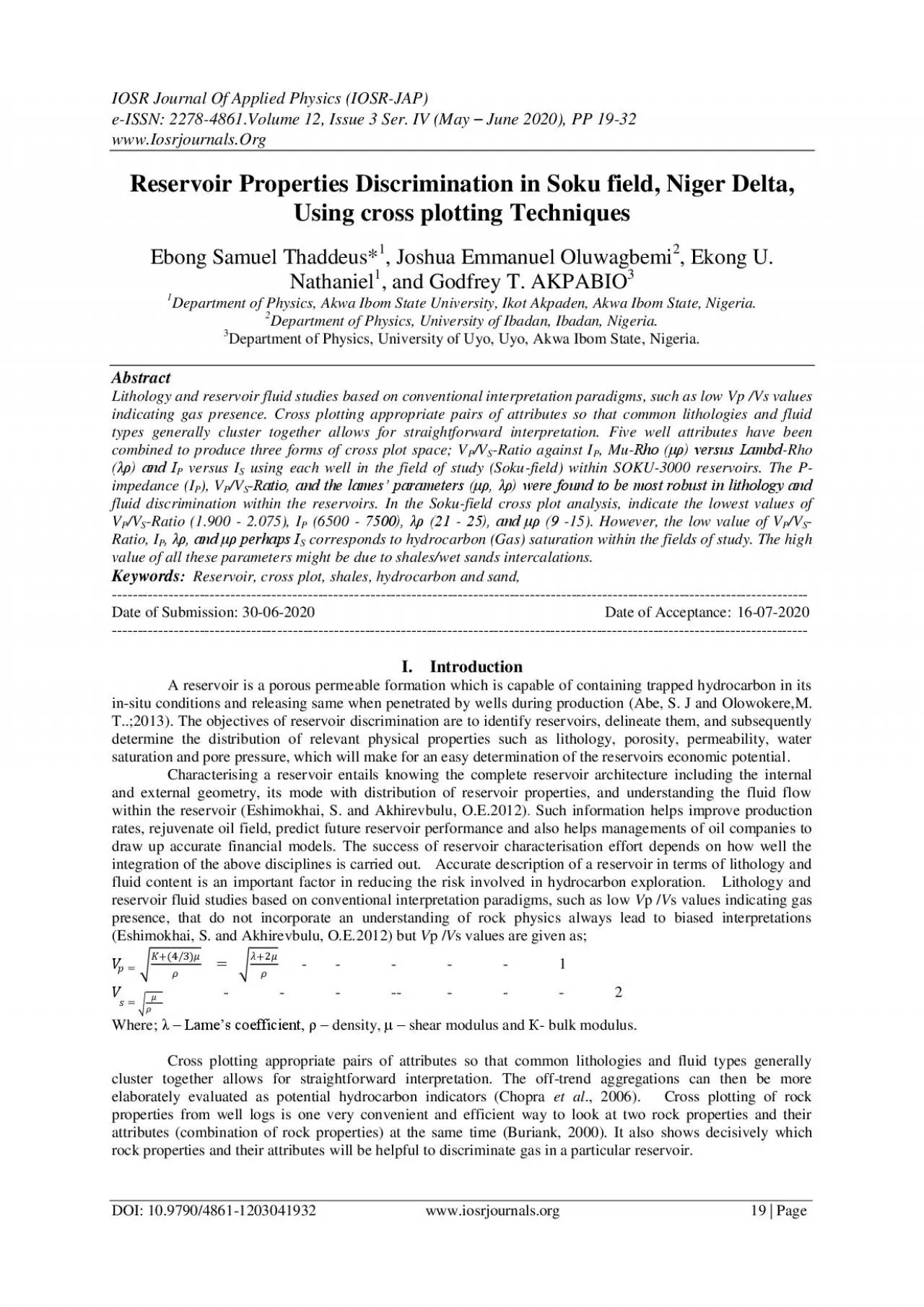
JAPeISSN 22784861Volume 12 Issue 3 Ser IVMay June 2020 PP 1932wwwIosrjournalsOrgDOI 10979048611203041932wwwiosrjournalsorg 19 PageReservoir Properties Discrimination in Soku field Nige ID: 858889

cross soku impedance reservoir soku cross reservoir impedance rho fluid field properties plot discrimination figure density delta high lithology

Share:

Link:

Embed:

Download Presentation from below link

Download Pdf The PPT/PDF document "IOSR Journal Of Applied Physics IOSR" is the property of its rightful owner. Permission is granted to download and print the materials on this web site for personal, non-commercial use only, and to display it on your personal computer provided you do not modify the materials and that you retain all copyright notices contained in the materials. By downloading content from our website, you accept the terms of this agreement.


Presentation Transcript

1 IOSR Journal Of Applied Physics (IOSR -
IOSR Journal Of Applied Physics (IOSR - JAP) e - ISSN: 2278 - 4861.Volume 12, Issue 3 Ser. I V (May – June 2020), PP 19 - 32 www.Iosrjournals.Org DOI: 10.9790/4861 - 12030 4 1932 www.iosrjo urnals.org 19 | Page Reservoir Properties Discrimination in Soku field, Niger Delta, Using cross plotting T echniques Ebong Samuel Thaddeus * 1 , Joshua Emmanuel Oluwagbemi 2 , Ekong U . Nathaniel 1 , and Godfrey T. AKPABIO 3 1 Department of Physics, Akwa Ibom State University, Ikot Akpaden, Akwa Ibom State, Nigeria. 2 Department of Physics, University of Ibadan, Ibadan, Nigeria. 3 Department of Physics, University of Uyo, Uyo, Akwa Ibom State , Nigeria. Abstract Lithology and reservoir fluid studies based on conventional interpretation paradigms, such as low V p / V s values indicating gas presence. Cross plotting appropriate pairs of attributes so that common lithologies and fluid types generally cluster together al lows for straightforward interpretation. Five well attributes have been combined to produce three forms of cross plot space; V P /V S - Ratio against I P , Mu - Rho (μρ) versus Lambd - Rho (λρ) and I P versus I S using each well in the field of study (Soku - field) withi n SOKU - 3000 reservoirs. The P - impedance (I P ), V P /V S - Ratio, and the lames’ parameters (μρ, λρ) were found to be most robust in lithology and fluid discrimination within the reservoirs. In the Soku - field cross plot analysis, indicate the lowest values of V P /V S - Ratio (1.900 - 2.075), I P (6500 - 7500), λρ (21 - 25), and μρ (9 - 15). However, the low value of V P /V S - Ratio, I P , λρ, and μρ perhaps I S corresponds to hydrocarbon (Gas) saturation within the fields of study. The high value of all these parameters might be due to shales/wet sands intercalations. Keywords : Reservoir, cross plot, shales, hydrocarbon and sand, ------------------------------------------------ ---------

2 ----------------------------------------
------------------------------------------------------------------------------ Date of Submission: 30 - 06 - 2020 Date of Acceptance: 1 6 - 07 - 2020 -------------------------------- ------------------------------------------------------------------------------------------------------- I. Introduction A reservoir is a porous permeable formation which is capable of containing trapped hydrocarbon in its in - situ conditions and releasing same when penetrated by wells during production (Abe, S. J and Olowokere, M. T..;2013). The objectives of reservoir discrimination are to identify reservoirs, delineate them, and subsequently determine the distribution of relevant physical propert ies such as lithology, porosity, permeability, water saturation and pore pressure, which will make for an easy determination of the reservoirs economic potential . Characterising a reservoir entails knowing the complete reservoir architecture including the internal and external geometry, its mode with distribution of reservoir properties, and understanding the fluid flow within the reservo ir ( Eshimokhai , S. and Akhirevbulu, O.E. 2012) . Such information helps improve production rates, rejuvenate oil field, pr edict future reservoir performance and also helps managements of oil companies to draw up accurate financial models. The success of reservoir characterisation effort depends on how well the integration of the above disciplines is carried out. Accurate de scription of a reservoir in terms of lithology and fluid content is an important factor in reducing the risk involved in hydrocarbon exploration. Lithology and reservoir fluid studies based on conventional interpretation paradigms, such as low V p / V s val ues indicating gas presence, that do not incorporate an understanding of rock physics always lead to biased interpretations ( Eshimokhai , S. and Akhirevbulu, O.E. 2012) but V p / V s values are given as; = + ( 4 / 3 ) = + 2 -

3 - - - - 1 =
- - - - 1 = - - - -- - - - 2 Where ; λ – Lame’s coefficient , ρ – density , μ – shear modulus and К - bulk modulus. Cross plotting appropriate pairs of attributes so that common lithologies and fluid types generally cluster together allows for straightfo rward interpretation. The off - trend aggregations can then be more elaborately evaluated as potential hydrocarbon indicators (Chopra et al ., 2006). Cross plotting of rock properties from well logs is one very convenient and efficient way to look at two rock properties and their attributes (combination of rock properties) at the same time (Buriank, 2000). It also shows decisively which rock properties and their attributes will be helpful to discriminate gas in a particular reservoir. Reservoir Properties Discrimination in Soku field, Niger Delta, Using cross plotting T echniques DOI: 10.9790/4861 - 12030 4 1932 www.iosrjo urnals.org 20 | Page II. Geology Of The Study Area The Niger Delta basin is situated along the southern end of Nigeria bordering the Atlantic Ocean between latitudes 4 0 E and 8 0 E a nd longitudes 4 0 N and 6 0 N. The Niger Delta is perhaps the most important sedimentary basin in sub - Sahara African due to its petroleum production, and it is one of the most important deltas in terms of its geology which is unique and classical ( Lehner, P., and De Ruiter, P.A.C., 1977). The onshore portion of the Niger Delta Province is delineated by the geology of southern Nigeria and southwestern Cameroon (figure 1). The northern boundary is the Benin flank -- an east - northeast trending hinge line south of t he West Africa basement massif. The northeastern boundary is defined by outcrops of the Cretaceous on the Abakaliki High and further east - south - east by the Calabar flank -- a hinge line bordering the adjacent Precambrian ( Doust, H., and Omatso la, E., 1990) . The offshore bounda

4 ry of the province is defined by the Ca
ry of the province is defined by the Cameroon volcanic line to the east, the eastern boundary of the Dahomey basin (the eastern - most West African transform - fault passive margin) to the west, and the two - kilometer sediment thickness conto ur or the 4000 - meter bathymetric contour in areas where sediment thickness is greater than two kilometers to the south and southwest. The province covers 300,000 km 2 and includes the geologic extent of the Tertiary Niger Delta (Akata - Agbada) Petroleum Syst em. Soku Oil field is part of OML 29. The field has several stacked reservoirs including the SOKU 3000 reservoi r analyzed in this study which is 98.25 ft thick. The Wells is labeled Soku 1, 2 and 3 as shown in figure 2; with inline and x - line value of 1675 - 1800 and 6260 - 6400 respectively from the base map of the survey area. Reservoir Properties Discrimination in Soku field, Niger Delta, Using cross plotting T echniques DOI: 10.9790/4861 - 12030 4 1932 www.iosrjo urnals.org 21 | Page Figure 2: Soku field with its base M ap. III. Materials And Method The methodology employed here examines the response of reservoir properties to the presence of hydrocarbons when rock properties are cross plotted. Next, the cross plots are closely observed, to identify the rock properties that are more robust than others in terms of sensitivity to either fluid or lithology, or both. These more robust properties are used in the iden tification and mapping of prospects. These attributes are computed from well log s. In the end, the results from the three stages are analyzed in other to determine fluid presence and discriminate lithology in the reservoirs. Data Sets Used : The data used in this work are well logs data from Soku field in the coastal swamp depobelt within the Niger Delta basin . These data were analysed using Hampson Russell Software (HRS) . The well log data was evaluated, and rock attribute cross - s

5 ections were generated . The importa
ections were generated . The importation of the well data was done through the use of e - Log application of the HRS in addition to their tops (SOKU - 3000) and check - shot corrections. The suite of wireline log data imported comprises of caliper log, gamma ray log, resistivity log, density log and sonic log. The inverse of the interval transit times of the sonic logs were used to generate the compressional velocities for each well. We generated S - wave data from Castagna´s relation using P - wave for well that did not h ave S - wave log. This recorded suite of logs can be grouped into two categories: properties that affect seismic wave propagation (example; compressional - and shear - velocity log and density log) and properties of interest for reservoir description but which indirectly affect seismic - wave propagation (example; porosity, water saturation, Vp/Vs ratio, P - impedance, S - impedance, Mu - rho and Lambda - rho logs). Below are the suites of logs used from the field. Reservoir Properties Discrimination in Soku field, Niger Delta, Using cross plotting T echniques DOI: 10.9790/4861 - 12030 4 1932 www.iosrjo urnals.org 22 | Page Figure 3: Suite of imported logs for Soku - 1 showing log signatures of Caliper(blue) Gamma ray, Resistivity, Density, P - wave, Check - shot and imported SOKU_3000 reservoir of interest. Figure 4 : Suite of imported logs for Soku - 2 showing log signatures of Caliper(blue) Gamma ray, Resistivity, Density, P - wave , Check - shot and imported SOKU_3000 reservoir of interest. Reservoir Properties Discrimination in Soku field, Niger Delta, Using cross plotting T echniques DOI: 10.9790/4861 - 12030 4 1932 www.iosrjo urnals.org 23 | Page Figure 5 : Suite of imported logs for Soku - 3 showing log signatures of Caliper(blue) Gamma ray, Resistivity, Density, P - wave, Check - shot and imported SOK

6 U_3000 reservoir of interest. Well
U_3000 reservoir of interest. Well Attributes Cross plots : Cross plots are visual representations of the relationship between two or more variables, and they are used to visually identify or detect anomalies which could be interpreted as the presence of hydrocarbon or other fluids and litho logies. This is carried out to determine the rock properties / attributes that better discriminate the reservoir (Omudu and Ebeniro, 200 5 ). The goal is to determine the feasibility of discriminating between reservoir fluids. To illustrate this point, the c ross plot of V P / V S ratio against acoustic impedance (AI) shows fluid as well as lithology discrimination along the acoustic impedance axis. It describes the conditions in terms of lithology and fluid content than V P / V S ratio. P - impedance and V P / V S ratio relationship discriminate both fluid and lithology. The V P / V S ratio is a fluid indicator because compressional waves are sensitive to fluid changes, whereas shear waves are not except in the special case of very viscous oil . P - impedance shows a bet ter discrimination which can better describe the reservoir conditions in terms of lithology and fluid content than the V P / V S ratio. Acoustic impedance versus V P / V S ratio contrast can show the position of gas - sand, water - sand and shale in V P / V S versus imped ance crossplot a s shown in figure 6 below. Figure 6 : Position of gas sand, water and shale in Vp/Vs versus acoustic impedance AI plot. (Source: Odegaar and Avseth, 2004) Reservoir Properties Discrimination in Soku field, Niger Delta, Using cross plotting T echniques DOI: 10.9790/4861 - 12030 4 1932 www.iosrjo urnals.org 24 | Page However, five well attributes were combined to produce three cross plots using each well in the field of study, within the chosen interval. These three cross plots (Vp/Vs ratio versus P - Impedance, Mu - Rho versus Lambda - Rho and P - Impedance versus S - Imp

7 ed ance) were used to discriminate from
ed ance) were used to discriminate from one well to the other probably what lithology/flui ds saturated in a given well through numbers of scatters each cross plot produced as shown figure 4.6a – 4.8c respectively. IV. Data Analysis, Result And Discussion We present results of this work which includes the identified reservoirs from logs, cross plots analysis from logs, rock attributes from Soku fi eld . The cross plots analyses are useful in differentiating between fluid and lithology in the reservoir (Omudu and Ebeniro, 2005). The corresponding cross section and horizon maps for some rock attribu te were investigated in order to map out regions in the field that would account for probable presence of gas sands, oil sands or brine sands in the fields of study. Well Log Analysis : The well curves used for the analysis are well logs of Soku - 1, Soku - 2 and Soku - 3 for m Soku field as shown in figure 8 a, 8 b and 8 c respectively . The logs include gamma ray overlay with caliper log , Porosity and Water Saturation logs. The true vertical depth (TVD) of each well ranges from 6126m to 11600 m, 6875m to 12100m and 6100m to 12000m for Soku - 1, Soku - 2 and Soku - 3 respectively. The reservoir of interest analyzed are SOKU - 3000 with thickness of 10400 - 10500m for (Soku - 1), 10428 - 10525m for (Soku - 2) and 10423 - 10516m for (Soku - 3) which are pre sent in the three wells in each field as shown in figure 7. Figure 7 : Correlation of sand lithologies ( SOKU - 3000) in Soku field using Gamma ray curves as guide However, the wells exhibit a dominantly shale/sand/shale sequence typical of the Niger delta formation. The wells were analysed in terms of fluid type and lithology within the zones of interest in which Shale lithologies were delineated by the high gamma ray (Shale lithologies cause the deflection of Gamma curve to the right) and resistivity to the far left due to its high conductive nature. Sand lithologies deflect the Gamma ray curve to the left and Resistivity curve to the

8 far right indicating probable hydrocarb
far right indicating probable hydrocarbon charged sand. Thus, Regions showing low gamma ray, high resistivity, high po rosities and low water saturation are mapped (circled) as sand lithologies with probable hydrocarbon zone in each well as shown figures below. On the other hand, regions showing high gamma ray, low resistivies, low porosities and high water saturation are mapped as shale lithologies. Reservoir Properties Discrimination in Soku field, Niger Delta, Using cross plotting T echniques DOI: 10.9790/4861 - 12030 4 1932 www.iosrjo urnals.org 25 | Page Figure 8 a: Soku - 1 suite of logs used in the analysis; low - Gamma ray, high - Resistivity, low - Density, low - P - wave, high - Porosity and low - Water Saturation with SOKU - 3000 having a thickness of 10400 - 10500m (100m). Figure 8 b: Soku - 2 suite of logs used in the analysis; low - Gamma ray, high - Resistivity, low - Density, low - P - wave, high - Porosity and low - Water Saturation with SOKU - 3000 having a thickness of 10428 - 10525m (97m). Reservoir Properties Discrimination in Soku field, Niger Delta, Using cross plotting T echniques DOI: 10.9790/4861 - 12030 4 1932 www.iosrjo urnals.org 26 | Page Figure 8 c: Soku - 3 suite of logs used in the analysis; low - Gamma ray, no change in (Resistivity, Density, P - wave, Porosity and Water Saturation) with SOKU - 3000 having a thickness of 10423 - 10516m (93m). Well Attributes Crossplot Analysis : Cross plot analysis was carried out to determine the rock properties / attributes that better discriminate the reservoir and to ascertain those attributes that are sensitive to 3D effects caused by changes in the reservoir fluid saturation and pressure (Om udu and Ebeniro, 2005). However, cross plots are visual representation of the relationship between any two variables which are used to detect significant departures from a back

9 ground trend; in other words to detect a
ground trend; in other words to detect anomalies which are related to lithology/ fluid contrasts. Elastic parameters mostly combined to delineate lithology/fluid clusters are V P /V S - Ratio and Acoustic Impedance because combination of these two is a good lithology fluid indicator (Avseth et al., 2005). Other elastic properties exist from the combination of Shear Impedance (SI) versus Acoustic Impedance (AI) and Lambda - Rho versus Mu - Rho cross plot proposed by ( Goodway et al . , 1997 ) used to improve petrophysical discrimination of rock properties. Three forms of cross plots are considered us ing five well derived attributes to delineate hydrocarbon/wet sa nd/shales clusters in each well w ithin the selected reservoirs ( SOKU - 300 ). This produces the cross plots in the field as shown below. CROSS PLOTS ANALYSIS / RESULTS (a). V P /V S - Ratio versus P - Impedance Cross Plot : The cross plot of V P /V S ratio against P - Impedance is shown in (Figure 9 a – 9c ), for souk well 1,2 and 3 which distinguishes reservoir sand (SOKU - 3000) into three lithologies using density as a color code; Hydrocarbon charged sands (dotted black eclipse) in which the low values of density (green to yellow – 2.0521 - 2.1202 g/cc) correspond to low values of Vp/Vs (1.950 - 2.050) and P - Impedance (5500 - 7000 m/s*g/cc); Wet sands (yellow eclipse) in which the moderately high values of densit y (brown to cyan – 2.1542 - 2.2563 g/cc) correspond to Vp/Vs (1.850 - 2.150) and P - Impedance (6750 - 8000 m/s*g/cc); Shales (blue eclipse) in which the high values of density (light blue - Purple – 2.2903 - 2.3924 g/cc) correspond to high values of Vp/Vs (1.850 - 2.15 0) and high values of P - Impedance (6750 - 8750 m/s*g/cc). This cross plot shows better fluid as well as lithology discrimination, indicating that V P /V S versus acoustic impedance attribute will better describe the reservoir conditions in terms of lithology an d fluid content; but note, a better discrimination/separation of clusters is o

10 bserved along the P - Impedance axis whi
bserved along the P - Impedance axis which discriminates between lithologies in the reservoir compared to Vp/Vs - ratio. SHALE LIT SOKU_3 000 Reservoir Properties Discrimination in Soku field, Niger Delta, Using cross plotting T echniques DOI: 10.9790/4861 - 12030 4 1932 www.iosrjo urnals.org 27 | Page Figure 9 a: V p /V s versus P - Impedance Cross Plot for Soku - 1 indicative of three anomalous sands mapped using density as a color code within the interval of SOKU - 3000. Figure 9b : V p /V s versus P - Impedance Cross Plot for Soku - 2 indicative of three anomalous sands mapped using density as a color code within the in terval of SOKU - 3000. Reservoir Properties Discrimination in Soku field, Niger Delta, Using cross plotting T echniques DOI: 10.9790/4861 - 12030 4 1932 www.iosrjo urnals.org 28 | Page Figure 9c : V p /V s versus P - Impedance Cross Plot for Soku - 3 indicative of three anomalous sands mapped using density as a color code within the interval of SOKU - 3000. (b). P - Impedance versus S - Impedance Cross plot : The cross plot of P - Impedance against S - Impedance is s hown in (Figure 10a – 10c ) respectively which distinguishes reservoir sand (SOKU - 3000) into two anomalous zones using density as a color code; Hydrocarbon charged sands (dotted black eclipse) in which the low values of density (green to yellow – 2.0521 - 2.1202 g/cc) correspond to low values of P - Imped ance (6500 - 7250 m/s*g/cc) and low values of S - Impedance (3200 - 3800 m/s*g/cc); Shales/wet zones (black eclipse) in which the high values of density (Red to Purple – 2.1542 - 2.3924 g/cc) correspond to high values of P - Impedance (6580 - 8500 m/s*g/cc) and high values of S - Impedance (3100 - 4500 m/s*g/cc). The cross plot shows that P - Impedance is a robust discriminator compared to S - Impedance. Figure 10a

11 : P - Impedance versus S - Impedance
: P - Impedance versus S - Impedance Cross Plot for Soku - 1 indicative of two anomalous zones mapped using density as a color code within the interval of SOKU - 3000. Reservoir Properties Discrimination in Soku field, Niger Delta, Using cross plotting T echniques DOI: 10.9790/4861 - 12030 4 1932 www.iosrjo urnals.org 29 | Page Figure 10 b: P - Impedance versus S - Impedance Cross Plot for Soku - 2 indicative of two anomalous zones mapped using density as a color code within the interval of SOKU - 3000. Figure 10c : P - Impedance versus S - Impedance Cross Plot for Soku - 3 indicative of two anomalous zones mapped using density as a color code within the interval of SOKU - 3000. (c). Mu - Rho versus Lambda - Rho Cross Plot : The cross plot of Mu - rho ( ) against Lambda - rho ( ) is shown in (Figure 11a – 11c) for souk well1,2and 3 which distinguishes reservoir sand (SOKU - 3000) into three lithologies/fluids contrasts using density as a color code; Gas zone (dotted black eclipse) in which the low values of density (green to yellow – 2.0521 - 2.1202 g/cc) correspond to low values of Mu - rho (9.50 - 14.0 GPa*g/cc) and low values of Lambda - rho (21.0 - 24.0 GPa*g/cc); fluids zone which could be probable Oil/Brine (yellow eclipse) in which the moderately high values of density (brown to cyan – 2.1542 - 2. 2563 g/cc) correspond to Mu - rho (10.10 - 16.0 GPa*g/cc) and Lambda - rho (24.5 - 28.0 GPa*g/cc); Shales (blue eclipse) in which the high values of density (light blue - Purple – 2.2903 - 2.3924 g/cc) correspond to high values of Mu - rho (10.5 - 20.5 GPa*g/cc) and high values of Lambda - rho (26.0 - 31.0 GPa*g/cc). This cross plot shows better fluid as well as lithology discrimination, indicating that lame’s constant attributes will better describe the reservoir conditions in terms of lithology and fluid content; but note, a better discrimination/separation of clusters is observed along the

12 Lambda - rho axis which discriminates b
Lambda - rho axis which discriminates between lithologies in the reservoir compared to Mu - rho. Reservoir Properties Discrimination in Soku field, Niger Delta, Using cross plotting T echniques DOI: 10.9790/4861 - 12030 4 1932 www.iosrjo urnals.org 30 | Page Figure 11a : Mu - Rho versus Lambda - Rho Cross Plot for Soku - 1 indicative of three anomalous fluid zones mapped using density as a color code within the interval of SOKU - 3000. Figure 11b : Mu - Rho versus Lambda - Rho Cross Plot for Soku - 2 indicative of three anomalous fluid zones mapped using density as a color code within the interval of SOKU - 30 00. Reservoir Properties Discrimination in Soku field, Niger Delta, Using cross plotting T echniques DOI: 10.9790/4861 - 12030 4 1932 www.iosrjo urnals.org 31 | Page Figure 11c : Mu - Rho versus Lambda - Rho Cross Plot for Soku - 3 indicative of three anomalous fluid zones mapped using density as a color code within the interval of SOKU - 3000. V. Interpretation And Discussion Five well attributes have been combined to produce three forms of cross plot space; V P /V S - Ratio against I P , Mu - Rho (μρ) versus Lambd - Rho (λρ) and I P versus I S using each well in the field of study , within SOKU - 3000 reservoirs. The P - impedance (I P ), V P /V S - Ratio, and the lames’ parameters (μρ, λρ) were found to be most robust in lithology and fluid discrimination within the reservoirs. In the Soku - field cross plot analysis, figure 9b and 11b ) indicate the lowest values of V P /V S - Ratio (1.900 - 2.075), I P (6500 - 7500), λρ (21 - 25), and μρ (9 - 15). However, the low value of V P /V S - Ratio, I P , λρ, and μρ perhaps I S corresponds to hydrocarbon (Gas) saturation within the fields of study. Also the high value of all these parameters might be due to shales/wet sands intercalations.

13 VI. Conclusion From the cross
VI. Conclusion From the cross plots analysis, Vp/Vs - ratio, P - impedance, Lamda - rho and Mu - rho attributes were found to be most robust in lithology and fluid discrimination within the reservoir. The Vp/Vs - Ip technique was able to identify gas sands in both fields because of the separatio n in responses of both Vp/Vs and Ip sections to gas sands versus shale. The Lambda - Mu - Rho (λ - μ - ρ) technique confirmed the gas sands delineation, because of the separation in responses of both λρ and μρ sections to gas sands versus shale. However, results from λ - μ - ρ inversion provided greater insight into rock properties for pore fluid and lithology discrimination by isolating Lame’ impedance parameters (Lambda - Rho (λρ) and Mu - Rho (μρ)) from the seismic reflectivity response. The combined interpretation o f Vp/Vs, Ip, Is, Lambda - Rho (λρ) and Mu - Rho (μρ) attributes from the post - stack 3D seismic data enhanced the identification and delineation of hydrocarbon charged sands with greater confidence. Low values of Lambda - Rho (λρ), Vp/Vs, Ip, associated with mod erate to high values of Mu - Rho (μρ), indicate the presence of hydrocarbons within the sand reservoirs ( SOKU - 3000). These results now confirm that this approach can be applied with confidence in delineating hydrocarbons sands in mature fields within the Nig er Delta basin and thereby increasing production from such fields. References [1]. Abe, S. J and Olowokere, M. T.(2013): Reservoir Characterisation and Formation Evaluation of some parts of Niger Delta using 3 - D seismic and well log data. Research Journal in Engineering and Applied Sciences 2(4) 304 - 307 [2]. Avseth P, mukerji T., and Marko G. (2005): Quantitative Seismic Interpretation Applying rock Physics to reduce interpretation risk, Cambridge University Press, Cambridge U.K. [3]. Burianyk, M., (2000): Amplitude - vs - offset and seismic rock property analysis: A primer: The Canadian Society of Exploration Geophysicist Recorder, 11, 1 - 14.

14 [4]. Chopra, S., Castgna, J., and Por
[4]. Chopra, S., Castgna, J., and Portniaguine, O., (2006): Thin - bed reflectivity inve rsion: The Canadian Society of Exploration Geophysicist Recorder, 01, 19 - 22 [5]. Doust, H., and Omatso la, E., (1990): Niger Delta, in Divergent/passive Margin Basins, AAPG Memoir 48: Tulsa, American association of Petroleum Geologists, p. 239 - 248. [6]. Eshimokhai, S. and Akhirevbulu, O.E.(2012): R eservoir Characterization using Seismic and Well logs data (a case study of Niger Delta), Ethiopian Journal of Environmental Studies and Management ( EJESM) Vol. 5 no.4 (Suppl.2) pp 597 - 603. [7]. Ekweozor, C. M., and Daukoru, E.M (1984), Petroleum source bed evaluation of Tertiary Niger Delta - reply: American Association of Petroleum Geologists Bulletin, v. 68, p. 390 - 394. Reservoir Properties Discrimination in Soku field, Niger Delta, Using cross plotting T echniques DOI: 10.9790/4861 - 12030 4 1932 www.iosrjo urnals.org 32 | Page [8]. Goodway, B., T. Chen, and J. Downton, (1997): Improved AVO fluid detect ion and lithology discrimination using Lame petrophysical parameters; ‘λρ', ‘μρ', & ‘λ/μ fluid stack' from P and S inversions: 67th Annual International Meeting, SEG, Expanded Abstracts, 183 - 186. [9]. Lehner, P., and De Ruiter, P.A.C., (1977): Structural h istory of Atlantic Margin of American association of Petroleum Geologies Bulletin, v. 61. p. 961 - 981. [10]. Odegaard, E. and P. Avseth, (2004): Well log and seismic data analysis using rock Physics templates. First Break 22 (10), 37 – 43 [11]. O mudu, L.M., and Ebeniro, J.O., 2005, Cross plot of rock properties for fluid discrimination, using well data in offshore Nige r Delta: Nigerian Journal of Physics, vol. 17, 16 - 20. Ebong Samuel Thaddeus , et . al . “ Reservoir Properties Discrimination in Soku field, Niger Delta, Using cross plotting Techniques . ” IOSR Journal of Applied Physics (IOSR - JAP) , 12( 3), 2020, pp. 19