PDF-Zeli Systems
3233 Pagosa Ct El Paso TX 79904
Phone 915 751 3222
FAX 915 751 3222
Z
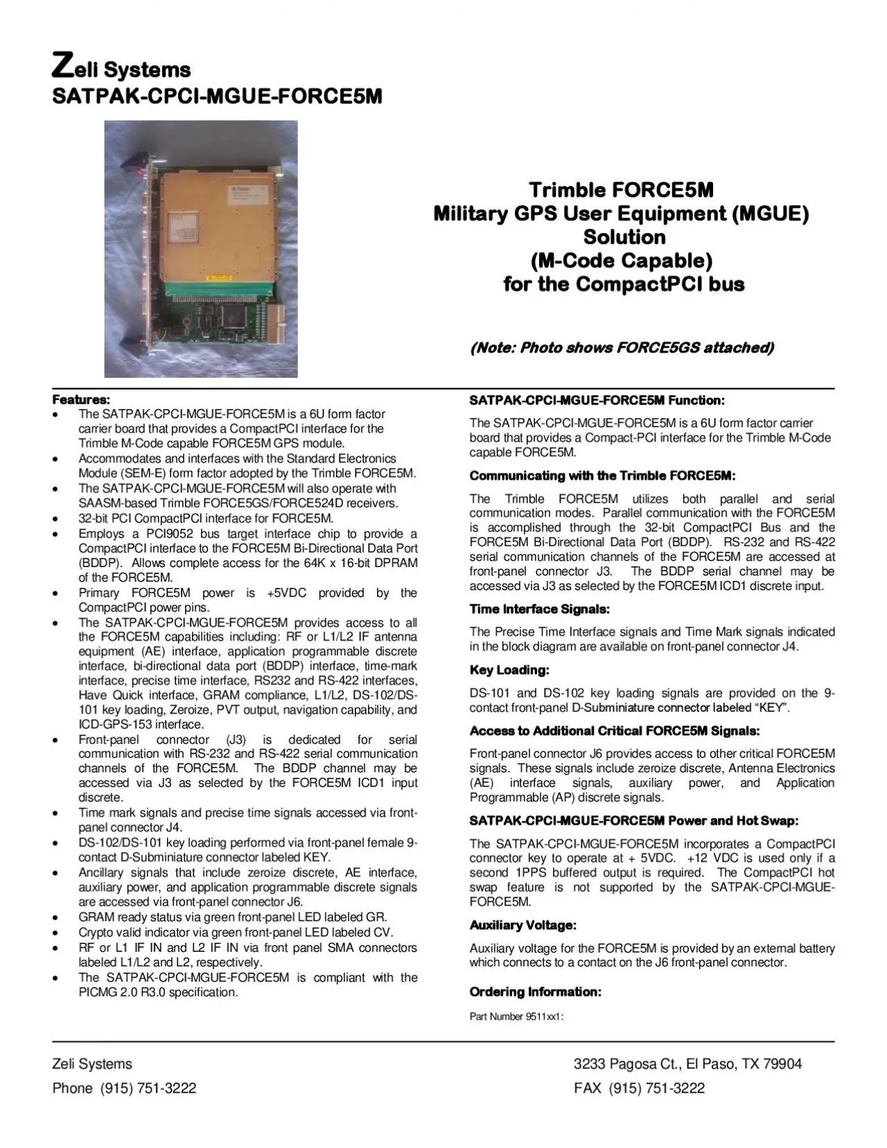
eli Systems
SATPAK CPCI MGUE FORCE5M
Features The SATPAK CPCI MGUE FORCE5M
is a 6U form factor
Download Presentation
"Zeli Systems" is the property of its rightful owner. Permission is granted to download and print materials on this website for personal, non-commercial use only, provided you retain all copyright notices. By downloading content from our website, you accept the terms of this agreement.
Presentation Transcript
Transcript not available.