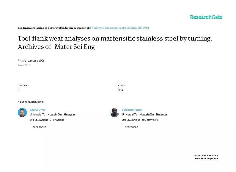
/
Abstract In this study, flank wear on CBN and PCBN tools due to cuttin Abstract In this study, flank wear on CBN and PCBN tools due to cuttin

Abstract In this study, flank wear on CBN and PCBN tools due to cuttin - PDF document

ellena-manuel
ellena-manuel . @ellena-manuel
Follow
398 views
Uploaded On 2016-04-15

Abstract In this study, flank wear on CBN and PCBN tools due to cuttin - PPT Presentation

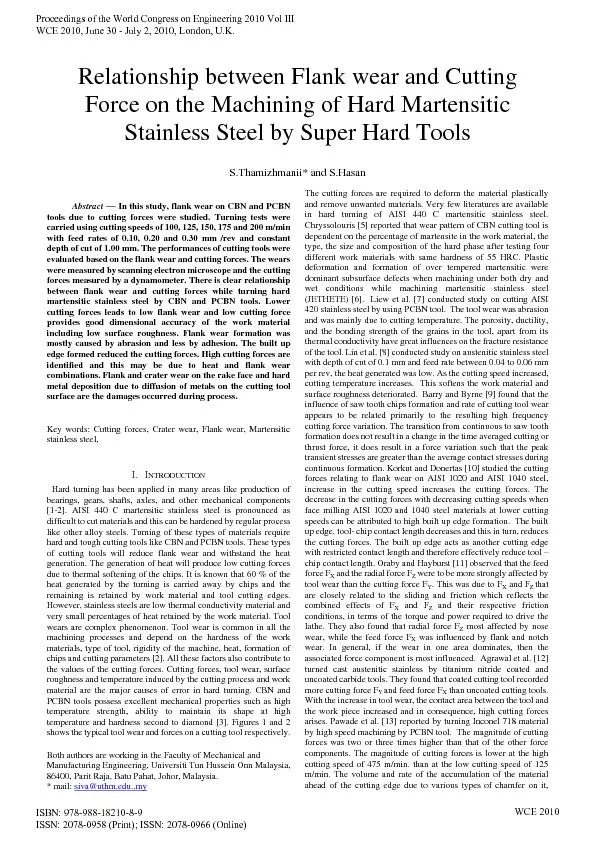
The cutting forces are required to deform the material plastically and remove unwanted materials Very few literatures are available in hard turning of AISI 440 C martensitic stainless steel Chryssol ID: 281197

The cutting forces are required

Share:

Link:

Embed:

Download Presentation from below link

Download Pdf The PPT/PDF document "Abstract In this study, flank wear on CB..." is the property of its rightful owner. Permission is granted to download and print the materials on this web site for personal, non-commercial use only, and to display it on your personal computer provided you do not modify the materials and that you retain all copyright notices contained in the materials. By downloading content from our website, you accept the terms of this agreement.


Presentation Transcript

Abstract In this study, flank wear on CBN and PCBN tools due to cutting forces were studied. Turning tests were carried using cutting speeds of 100, 125, 150, 175 and 200 m/min with feed rates of 0.10, 0.20 and 0.30 mm /rev and constant depth of cut of 1.00 mm. The performances of cutting tools were evaluated based on the flank wear and cutting forces. The wears were measured by scanning electron microscope and the cutting forces measured by a dynamometer. There is clear relationship between flank wear and cutting forces while turning hard martensitic stainless steel by CBN and PCBN tools. Lower cutting forces leads to low flank wear and low cutting force provides good dimensional accuracy of the work material The cutting forces are required to deform the material plastically and remove unwanted materials. Very few literatures are available in hard turning of AISI 440 C martensitic stainless steel. Chryssolouris [5] reported that wear pattern of CBN cutting tool is dependent on the percentage of martensite in the work material, the type, the size and composition of the hard phase after testing four Proceedings of the World Congress on Engineering 2010 Vol III WCE 2010, June 30 - July 2, 2010, London, U.K. ISBN: 978-988-18210-8-9 ISSN: 2078-0958 (Print); ISSN: 2078-0966 (Online) WCE 2010 influences the magnitude of the cutting forces to a great extent. Qian and Hossan [14] reported that the effect of cutting forces in turning hardened tool steels with CBN tool during machining of hard AISI ed with the increase of feed rate due to an increase in the chip load. The increasing trend of forces with increasing cutting speeds, feed rate, tool nose radius, negative rake angles and work piece hardness. Calamaz et al. [15] observed that the titanium alloy is difficult to cut materials that often as saw tooth chips at relatively low cutting speeds. The chip segmentation affects the machining process – cutting forces, temperature, and work piece quality, EXPERIMENTALA. Stainless steel AISI 410, 420 and 440 A, B, C are all considered as martensitic stainless steel and can be hardened like other alloy steels. In this used under hard condition. AISI 440 C is widely used in aerospace industries for bearings, steam and pumps, turbines, compressor components, shafting, cutlery, surgical tools,plastic moulds, nuclearapplications etc.gh resistance to wear and corrosion [16]. It has high viscosity, poor thermal conductivity,rate and tendency to form built up edge (BUE) at tool edge. AIgroup [17]. The materials were received as 50 mm diameter and 1000 mm length. They are cut to 300 mm length and skin turned to remove oxide formation. The work pieces were centered on both sides to accommodate in the lathe centers. The heat treatment was carried by induction hardenimaintained between 45 to 55 HRC. The chemical and mechanical properties are shown in the tables 1 and 2 respectively. The turning experiments were conducted using on NC Harrison 400 Alpha Lathe with 7.5 kw capacity. The cutting tools have three 5 times. The test conducted by each cutting edge was termed as trial 1, 2, 3, 4 and 5. Five cutting 200 m/min with feed rates of have been selected. The length ofwere performed under continuous turning conditions with dry turning. The cutting forces component F were measured on line by Kistler dynamometer type 9265 B with data acquisition system. Each and every trial the flank wmeasured by SEM and diffusion by EDS analyses. The cutting e tool flank wear of 0.30 mm manufactured by Mitsubishi and PCBN tool is by Kennametal. The tool holder used was by MTJNR 2020 KL16N by Mitsubishi. Table1. Chemical composition of AISI 440 C stainless steel MateriaSi % P % S % 1.00 1.00 16-18 0.75 Table2. Mechanical properties of AISI 440 C stainless steel % of elongation AISI 440 C 1965 1900 Figure1: Typical tool wear on a single point tool [3] Figure 2: Forces action on a tool [4] A. Flank wearWhile turning for 150 mm length of turning at cutting velocities of feed rates of 0.10, 0.2 and 0.30 mm/rev, there were initial flank wear due to sharp cutting However, the flank wear by CBN tool was more at feed rate of 0.10 mm /rev than feed rate of ear by PCBN tool was less than CBN tool. At feed rate of 0.20 mm/ rev, flank wear was less than 0.10 feed rate and far less by fcutting velocities were increased, the rate of flank wear also increased in all feed rates both by CBN and PCBN tools. At high feed rate, the flank wear was less. This is shown in the figure 3 a. As the length of turning continued foby CBN tool continued to increase. The flank wear was low at feed rate of 0.10 mm/rev but increases The flank wear formation rate of CBN tool is always higher than PCBN tool. The maximum flank wear 0.30 mm was exceeded at cutting velocity of 200 m/min with feed rate of 0.10 mm/ rev for the length of 750 mm and it was 0.342 mm. flank wear rates were 0.311 and 0.231 mm by CBN tool respectively. On contrary, PCBN tool recorded flank wear of 0.126 mm at cutting velocity of 200 m/min with feed rate of 0.10 mm/rev. Fla0.30 mm /rev were 0.122 and 0.106 mm respectively at the end of 750 mm length turning. Figure 3 a to e show flank wear formed at various length of turning. The study showed that flank wear occurs much earlier on CBN tools than PCBN tools. In CBN tool, flank wear chipping and built up edges occurred. Korkut et al. [17] studied the tool wear formation by AISIof heat by turning is not dissipated rapidly due to the low thermal conductivity. The flank wear formation was much affected by heat when the area of flank side increased. Flank area was increased, rubbing action was more. The increased flank area increase the heat generation at low cutting velocity. The generated heat was shared by increased the wear. Many researches studied the effect of chip affecting the wear of the tool. It cutting velocities the flank wear increased clearly and the flank wear is caused by abrasion. The chipping occurred due to high cutting temperature and the pressure on the tool tip is the main cause were observed both on CBN and PCBN tools. The formation of built up edges on PCBN tool was low in size than CBN tool. This was due the characteristics of the stainless steel material. At high cutting velocities, the built up edges break and disappeared. From the SEM examination, wear were due ools. However, the intensity of formation was low in PCBN tool than CBN tool. The element of Fe was observed on CBN and PCBN toolwell by diffusion. Many researcherchips were formed while machining difficult to cut materials like stainless steel and in these test there was also the formation of saw parameters by both cutting tools. The saw tooth chips had rough surface and it abraded the flank wear the rake face of the tool causing crater wear. The diffusion of work material was found on the crater and diffusion is a chemically activated process due to tribo-chemical reactions occurring at high temperature. The EDS analyses, confirms that material transfer take places as a result of chemical affinity between the work material and tools, which accelerate the rise in temperature at tool – chip interface and therefore responsible for layer formation. Flank wear cutting edge was due to heat at t tools were able to withstand more generated heat than CBN tools. The flank wear and crater wear were the dominant tool wear typedominant wear mechanisms on both CBN and PCBN tools. Figure 5 (a) to (c) are the SEM images on flank wear and 5 (d) to (e) are for the crater wear by CBN tool. Diffusion of work material was seen on the crater on the rake face as shown in the Figure 5 (d) to (e). Built up edges were noted both by CBN and PCBN tools, however, the sizes were different. The chipping by CBN tool is shown in the Figure 5 (h) and this was due to high temperature and load at cutting edge. Figure 6 (a) to (h) are the SEM images on PCBN tool. There was a thick layer of work material on the rake face of tool which prevents crater to form. The notch wear formed at the end of the tests. The flank wear by PCBN noticed on the rake face of the tool by EDX analysis and shown in Cutting Force Force is required to deform the material plastically though there is a dependency on certain factors. The cutting forces are very sensitive to chemical composition, hardness, micro-structure, type of cutting tools used, machine stability, heat generation and tool which is shown in the Figure 2. One of the most promising tool wear appears to be the measurement of cutting forces. Force signals are highly sensitive hence, they are the best alternatives to tool wear monitoring [18]. During machining any ductile materials, heat is generated at the (a) primary deformation zone due to sh deformation and sliding and (c) work – tool interfaces due to rmaximum temperature at the chip-tool interface which substantially influences the chip formation modeof the three forces acting, cutting force was more than other two forces. However, depending upon the wear of the tool, forces may vary. The cutting force F was affected by flank wear and crater wear and this may affect the feed force F and radial forces Fmeasured cutting forces for both CBN and PCBN tool inserts are given in Figure 4 (a) to (e). When the feed rate increased with the increase of cutting velocities, high forces were required to deform the material within short period of time. This raises the high temperature at tool tip – work material interface. The heat generated was carried away by the chips rather than retention by work material. Some amount of heat was retained by the tool tip. Increase in the feed rate increases the cutting force. The removal of material take place in a short time for a given length required high cutting forces. The removal of material increased the plastic deformation and also generated more heat. 100125150175200Cutting velocity-length 150 mm Flank wear CBN-0.10 CBN-0.20 CBN-0.30 PCBN-0.10 PCBN-0.20 PCBN-0.30 0.050.10.150.2100125150175200Cutting velocity - length 300 mm Flank wear CBN-0.10 CBN-0.20 CBN-0.30 PCBN-0.10 PCBN-0.20 PCBN-0.30 Figure 3: Cutting velocity Vs flank wear for – a. 150, b. 300, c. 450, d. 600 and e. 750 mm length of turning. 100125150175200Cutting velocity-length 600 mmFlank wear CBN-0.10 CBN-0.20 CBN-0.30 PCBN-0.10 PCBN-0.20 PCBN-0.30 100125150175200Cutting velocity- length 450 mmFlank wear CBN-0.10 CBN-0.20 CBN-0.30 PCBN-0.10 PCBN-0.20 PCBN-0.30 100125150175200Cutting velocity-length 750 mmFlank wear CBN-0.10 CBN-0.20 CBN-0.30 PCBN-0.10 PCBN-0.20 PCBN-0.30 100125150175200Cutting velocity-length 150 mmCutting force Fy -N CBN-0.10 CBN-0.20 CBN-0.30 PCBN-0.10 PCBN-0.20 PCBN-0.30 100125150175200Cutting velocity-length 300 mmCutting force Fy-N CBN-0.10 CBN-0.20 CBN-0.30 PCBN-0.10 PCBN-0.20 PCBN-0.30 100125150175200Cutting velocity -length 450 mm Cutting force Fy-N CBN-0.10 CBN-0.20 CBN-0.30 PCBN-0.10 PCBN-0.20 PCBN-0.30 Figure 4: Cutting velocity Vs cutting force Fy- a. 150, b. 300, c. 450, d. 600 and e. 750 mm length of turning (a) (b) (c) (d) (e) (f) Figure 5: SEM images on CBN tool. (a) (b) 100125150175200Cutting velocity-length 750 mm Cutting force Fy-N CBN-0.10 CBN-0.20 CBN-0.30 PCBN-0.10 PCBN-0.20 PCBN-0.30 100125150175200Cutting velocity - length 600 mm Cutting force Fy-N CBN-0.10 CBN-0.20 CBN-0.30 PCBN-0.10 PCBN-0.20 PCBN-0.30 (e) (f) (g) (h) Figure 6: Flank and crater wear by SEM on PCBN tool. SEM images show built up edges were formed in all the cutting parameters at low cutting velocities, which decrease the cutting forces. The built up edge acts like another cutting edge even though the built up edge is small in sizes and reduces the cutting force. The best way to reduce the built up edge is to increase the cutting velocity and make it as unstable. This breaks the built up edges and carried along with the chips. The built up edge decreased the tool – chip contact length and in turn reduces the cutting force. Cutting rate due to an There is clear relationship between flank wear and cutting forces while turning hard martensitic stainless steel by CBN and PCBN tools. The lower thflank wear and low cutting force provides good dimensional accuracy of the work material including the surface roughness. Flank wear formation was more by abrasion rather than by adhesion. The built up edge formed reduced eat at cutting zone. Flank wear and crater on the rake face and hard metal depositions on the cutting tool surface are the damage that takes place during higher the friction of the tool on the work material and high heat generation occurred. ACKNOWLEDGMENT The authors would like to thank the Universiti Tun Hussein Onn Malaysia and Ministry of Higher Education Malaysia for financial support vide - Vot 0129 and 0372. [1] W.Grzesik, Influence of t hard turning using different shaped ceramic tools, Wear, (2007), doi:10.116/j.wear.11.001. [2] S.Thamizhmanii and S. Hasan, Measurement of surface roughness and flank wear on hard martensPCBN cutting tools, Journal of Achievements in Materials and Manufacturing Engineering, Volume 31, (2008), Issue 2. [3] M.P.Groover, Fundamentals of modern Manufacturing, John Wiley and sons, Edition 2007. [4] N.A.Abukhshim, P.T.Matinvenga, and M.A. Sheikh, (2005). in high speed turning of high strength alloy steel. International Journal of Machine Tools and Manufacture, 45, (2005), 1687-1695. [5] G. Chryssolouris, Turning of hardened steels using CBN tools. Journal of Metal Working, Volume 2, (1982), pp.100-106. [6] E.O.Ezugwu, and K.A. Olajire, Evaluation of machining performance of martensitic stainless steel. Tribology Letters, Volume 12, (2002), No.4. [7] W.Y.H. Liew, B.K.A Ngoi, and Y.G.Lu, Wear characteristics of PCBN tools in the ultra – precision machining of stainless steel at low speeds. Wear, (2003), 254, 265-277. [8] W.Y.H. Liew, S.Yuan, and B.K.A Ngoi, Evaluation of machining performance of STAVAX with PCBN tools. International Journal Advanced Manufacturing Technology, 23, 11-29, (2004), doi: 10.1007/s 00170-1520-y. [9] J. Barry, and G. Byrne, Cutting tool wear in the machining of hardened steels, Part I, Cubic boron nitride cutting tool. Wear, (2001), 247, 139-151. [10] I. Korkut, and M.A. Donertas, The influence of feed rate and cutting speed on the cutting forces, surface roughness and tool – chip contact length during face milling. Materials and Design 28, (2007), 308-312. [11] S.E. Oraby, and D.R. Hayburst, Tool life determination based on the measurement of wear and tool force ratio variation. International Journal of Machine Tools and Manufacture, 44, (2004), 1261- 1269. [12] S. Agrawal, A.K.Chakrabarti, and Chattopadhyay, A study of the machining of austenitic stainless stof Materials Processing Technology 52, (1995), pp.610-620. [13] P.S.Pawade, S.Suhas, Joshi. P.K.Brahmankar, and M.Rahman, An investigation of cutting forces and surface damage in high speed turning of Inconel 718. Journal of Materials Processing Technology, (2007), doi: 10.1016/j, jmat protec.2007.04.049. [14] Li Qian and Mohammad Hossan, Effect of cutting force in turning hardened tool steels with CBN inserts. Journal of MaterialsProcessing Technology, 191, (2007), 274-278. [15] M. Calamaz, D. Coupard, and Franck Girot, A new model for 2D numerical simulation of serrated chip formation when machining titanium alloy Ti-6Al-4V. Internaand Manufacture, 48, (2008), 275-288. [16] C. T.Kwok, K.H.Lo, F.T.Cheng and H.C.Man, Effects of processing condition on the corrosion performance of Laser surface melted AISI 440 C martensitic stainless steel, Surface and Coatings Technology, 166, pp.84-90, 2003. [17] K.H.Lo, F.T.Cheng, C.T.Kowk and H.C.Man, Effects of laser treatments on cavitations erosion and corrosion of AISI 440 C martensitic stainless steel, Materi[18] I.Korkut, Mustafa Kasap, Ibrahim Ciftci and Ulvi Sekar, Determination of optimum cutting parameters during machining steel, Materials and Design 25, (2004), 303-305. [19] S.K.Choudhury and K.K.Kishore, Tool wear measurement in turning using force ratio, International Journal of Machine Tools and Manufacture, 40 (2000), 899-909. ISBN: 978-988-18210-8-9 ISSN: 2078-0958 (Print); ISSN: 2078-0966 (Online) WCE 2010 Proceedings of the World Congress on Engineering 2010 Vol III WCE 2010, June 30 - July 2, 2010, London, U.K.