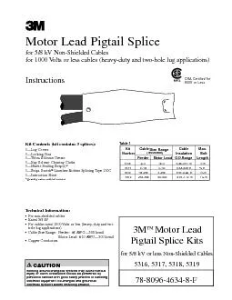
/
Motor Lead Pigtail Splicefor 5/8 kV Non-Shielded Cablesfor 1000 Volts Motor Lead Pigtail Splicefor 5/8 kV Non-Shielded Cablesfor 1000 Volts

Motor Lead Pigtail Splicefor 5/8 kV Non-Shielded Cablesfor 1000 Volts - PDF document

ellena-manuel
ellena-manuel . @ellena-manuel
Follow
387 views
Uploaded On 2017-03-04

Motor Lead Pigtail Splicefor 5/8 kV Non-Shielded Cablesfor 1000 Volts - PPT Presentation

Kit Contents kit contains 3 splices3151Lug Covers3151Locking Pins3151Tubes Silicone Grease3151Bag Solvent Cleaning Cloths3151Mastic Sealing Strips Strips ScotchSplicing Tape 31 ID: 522249

Kit Contents (kit contains

Share:

Link:

Embed:

Download Presentation from below link

Download Pdf The PPT/PDF document "Motor Lead Pigtail Splicefor 5/8 kV Non-..." is the property of its rightful owner. Permission is granted to download and print the materials on this web site for personal, non-commercial use only, and to display it on your personal computer provided you do not modify the materials and that you retain all copyright notices contained in the materials. By downloading content from our website, you accept the terms of this agreement.


Presentation Transcript

Motor Lead Pigtail Splicefor 5/8 kV Non-Shielded Cablesfor 1000 Volts or less cables (heavy-duty and two-hole lug applications) Kit Contents (kit contains 3 splices):3—Lug Covers3—Locking Pins3—Tubes Silicone Grease3—Bag Solvent Cleaning Cloths3—Mastic Sealing Strip(s)* Strips ScotchSplicing Tape 3—Instruction Sheet*Quantity varies with kit number. Kit Cable Size Range Cable Max. Number (AWG/kcmil) Feeder Motor Lead O.D. Range Length 5316 8–4 10–4 0.30–0.51 in. 5317 2–1/0 4–1/0 0.43–0.65 in. 5318 1/0–250 2–250 0.53–0.88 in. 1 5319 250–500 4/0–500 0.75–1.12 in. 1 in. 3M™ Motor Lead Pigtail Splice Kitsfor 5/8 kV or less Non-Shielded Cables5316, 5317, 5318, 5319 Technical Information: For non-shielded cables Rated 5/8 kV For cables rated 1000 Volts or less (heavy-duty and two hole lug applications) Cable Size Range: Feeder: #8 AWG—500 kcmil Motor Lead: #10 AWG—500 kcmil Copper Conductors CSA Certified for 600V or Table 1 CAUTIONWorking around energized systems may cause serious injury or death. Installation should be performed by personnel familiar with good safety practice in handling electrical equipment. De-energize and ground all electrical systems before installing product. 2 78-8096-4634-8-F Linerless Rubber Splicing Tape 130C Figure 11.0 Prepare Cable According to Standard Procedures Check to be sure cables fit within cable kit range as shown in Table 1 on cover. Remove cable insulation for length recommended by terminal lug manufacturer; if no information is available, remove fordepth of lug barrel. Install Lugs Install and crimp lugs per manufacturer’s direction. See back page if 3M Scotchlok Copper Lugs are used. Clean insulation for approximately 6 using solvent saturated cloths provided in kit. FOR 8kV ONLY. Fill lug/insulation gaps with Scotch Linerless Rubber Splicing Bolt lugs together. See Table 1 on cover for maximum bolt length. See Figure 2 for proper bolt/lug arrangement. Install Lug Cover Separate cables and apply mastic strip between and around them, " from ends of cable insulations (Figure 3).mastic to an overall diameter that is greater than the inside diameter of the Lug Cover.Press cables together and make certain that no void exists between them (Figure 3).Overwrap the mastic with 1 or 2 wraps of vinyl tape (Figure 3). Figure3 78-8096-4634-8-F 3 Scotch® Linerless Rubber Splicing Tape 130C Figure 4 Figure 3.3 FOR 8 kV ONLY. Cover the lugs and bolt with four half-lapped layers of ScotchNote: Lug cover will be printed with 5 kV rating. Mastic layer qualifies the part as 8 kV. Install Lug Cover. Position Lug Cover so the punch holes are positioned between the cables (Figure 5). The kit contains a small tube of Silicone Grease. Use it to lightly lubricate the mastic and vinyl tape wraps. This will aid in the installation of the Lug Cover. Be sure that the punched holes are beyond the cable end of the mastic and vinyl tape wrap. Insert the plastic locking pin through the holes (Figure 5).Hint: Inserting the pin from the back side of the Lug Cover will aid in visually aligning the pin through both holes.3.6 Cut off excess pin length, if desired. (Leave at least " extending from Lug Cover). Tooling IndexInformationforScotchlokTwo Copper Lugs TOOL-DIE Cable Stud Scotchlok Size Size CopperLug BurndyCorporation ThomasCorporation AndersonDiv. NumberY34A Y35,Y39, TBM5 TBM8 TBM15 VC6–3 Y45*,Y46* VC6–FT** 10 30014 6 1/4 30015 6AWG(1) U5CRT(1) Blue(1) Blue(1) Universal 5/16 30016 10 300181/4 30019 W161(1) 4AWG(1) A4CR(1) U4CRT(1) Grey(1) Grey(1) Universal 3/8 30021 1/4 300225/16 30023 W162(2) 2AWG(1) A2CR(1) U2CRT(2) Brown(1) Brown(1) 33(1) Universal 3/8 30024 5/16 300273/8 30028 1AWG(1) A1CR(1) U1CRT(2) Green(1) Green(1) 37(1) Universal 5/16 30031 1/0 3/8 30032 W163(2) 1/0(1) A25R(1) U25RT(1) Pink(2) Pink(2) 42H(2) Universal 2/0 3/8 30036 W241(2) 2/0(1) A26R(1) U26RT(2) Black(2) Black(2) 45(1) Universal 3/0 1/2 30041 W243(2) 3/0(1) A27R(1) U27RT(2) Orange(2) Orange(2) 50(1) Universal 1/2 30045 BG(3) 4/0(1) U28RT(3) Purple(2) Purple(2) 54H(2) Universal 4/0 1/2 31145 BG(4) 4/0(2) U28RT(2) Purple(3) Purple(3) 54H(3) Universal 250 1/2 31149 W166(4) 250(2) A29R(2) U29RT(3) Yellow(2) Yellow(2) 62(2) Universal 300 1/2 31153 A30R(2) U30RT(3) White(3) 66 (3) Univ 350 1/2 31156 A31R(2) U31RT(3) Red(4) 71H 400 1/2 31160 A32R(2) U32RT(3) Blue(4) 76H 500 1/2 31166 A34R(2) U34RT(3) Brown(4) 87H *Y45 and Y46 accept all Y35 dies (“U” series). For Y45 use PT6515 adapter. For Y46 use PUADP adapter.**Anderson VC6–3 and VC6–FT require no die set.3M, Scotch and Scotchlok are trademarks of 3M Company.Important NoticeAll statements, technical information, and recommendations related to 3M’s products are based on information believed to be reliable, but the accuracy or complete-ness is not guaranteed. Before using this product, you must evaluate it and determine if it is suitable for your intended application. You assume all risks and liability associated with such use. Any statements related to the product which are not contained in 3M’s current publications, or any contrary statements contained on your purchase order shall have no force or effect unless expressly agreed upon, in writing, by an authorized officer of 3M.Warranty; Limited Remedy; Limited Liability This product will be free from defects in material and manufacture for a period of one (1) year from the time of purchase. 3M MAKES NO OTHER WARRANTIES INCLUDING, BUT NOT LIMITED TO, ANY IMPLIED WARRANTY OF MERCHANTABILITY OR FITNESS FOR A PARTICULAR PURPOSE. If this product is defective within the warranty period stated above, your exclusive remedy shall be, at 3M’s option, to replace or repair the 3M product or refund the purchase price of the 3M product. Except where prohibited by law, 3M will not be liable for any indirect, special, incidental or consequential loss or damage arising from this 3M product, regardless of the legal theory asserted.6801 River Place Blvd. Austin, TX 78726-9000 Fax 800-245-0329www.3M.com/electricalPlease recycle. . All rights reserved.