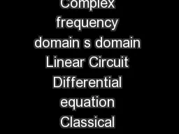
/
SDomain Analysis  sDomain Circuit Analysis Time domain t domain Complex frequency domain SDomain Analysis  sDomain Circuit Analysis Time domain t domain Complex frequency domain

SDomain Analysis sDomain Circuit Analysis Time domain t domain Complex frequency domain - PDF document

ellena-manuel
ellena-manuel . @ellena-manuel
Follow
750 views
Uploaded On 2015-01-18

SDomain Analysis sDomain Circuit Analysis Time domain t domain Complex frequency domain - PPT Presentation

Identify a node voltage at each of the nonreference nodes and a current with every element in the circuit Step 2 Write KCL connection constraints in terms of the element currents at the nonreference nodes Step 3 Use the element admittances and the f ID: 33046

Identify node voltage

Share:

Link:

Embed:

Download Presentation from below link

Download Pdf The PPT/PDF document "SDomain Analysis sDomain Circuit Analys..." is the property of its rightful owner. Permission is granted to download and print the materials on this web site for personal, non-commercial use only, and to display it on your personal computer provided you do not modify the materials and that you retain all copyright notices contained in the materials. By downloading content from our website, you accept the terms of this agreement.


Presentation Transcript

S-Domain Analysis s-Domain Circuit AnalysisTime domain DifferentialLaplace TransformInverse Transform Laplace Transform Transformed Kirchhoff’s Laws in s-Domaint domains domain )(1ti)(4ti)(2ti)(3ti0)()()()(4321titititi0)()()()(4321sIsIsIsI0)()()(321tvtvtv0)()()(321sVsVsV )(2tv)(4tv)(1tv)(3tv)(5tv Signal Sources in s Domain L t domains domain _+)(tvS _+ )(ti()()(titvtvSVoltage Source: _+)(sV)(sVS _+ )(sIVoltage Source:circuit()()(sIsVsVS +_)(tv)(tiS )(ti()()(tvtitiSCurrent Source: )(sV )(sIS +_ )(sICurrent Source:circuit()()(sVsVsIS Time and s-Domain Element ModelsImpedance and Voltage Source for Initial ConditionsTime Domain L s-Domain +)(tvRR Resistor: +)(sVRR Resistor: +)(tvLL )(tiL tvLL)()( + _+)(sVLLs)0(L (sIL)0( ()(LLLV +)(tvCC )(tiC )0( (1)(0CtCCvdiCtv + _+)(sVC Cs1 svC)0( )(sIC s)(vsIVCCC0 (1)( Impedance and Voltage Source for Initial Conditions sIsVsZRRR)()()( 0)0(th ()()(LLLLiIsVsZ •Impedance Z(s) •Impedance of the three passive elements Time and s-Domain Element ModelsAdmittance and Current Source for Initial ConditionsTime Domain L s-Domain +)(tvRR )(tiR Resistor: +)(sVRR )(sIR Resistor: +)(tvLL )(tiL 0( (1)(0LtLLidvLti _+)(tvCC )(tiC tiCC)()( )(isVILLL0 (1)( _+)(sVLLs siL)0( )(sIL )0( ()(CCCI +)(sVC Cs1)0(C (sIC Admittance and Current Source for Initial sVsIsYRRR1)()()( 0)0(th )()()(LLLLiVsIsY •Admittance Y(s) •Admittance of the three passive elements Example: Solve for Current Waveform i(t) L + )(tuVAR)(tiL _+)(sVL)0(LLi)(sVR _+ sVAR)(sILs _+ 0)()(sVsVsVLRABy KVL:)()(sVR0()()(LLLisLsIsV )0()()(LAV LRsiLRsRVsRVLRsiLRssLVsILAALA)0()0()()( Inverse Transform:forced response Series Equivalence and Voltage Division ()()()()()()()(2211sVsZsZsVsVsZsZsVEQ)()()()()(2222sIsZsIsZsV)()()(21sZsZsZ 1 2 )(1sV )(2sV)(sV)(sI )(1sI )(2sI )(sV)(sI 21ZZZ Parallel Equivalence and Current Division ()()()()()()()(2211sIsYsYsIsIsYsYsIEQ)()()(22sVsYsI)()()(21sYsYsY )(sV)(sI 21YYY 1 2 )(sV)(sI )(2sI )(1sI )(1sV1EQZ _+_+Ls (2sV A B Z (1sV _+ A B Z (1sV1EQZ _+_+Ls (2sV A B Example: 11)()(21RLCsRCsZZEQ CssZsYEQ1)(1)(11 Find equivalent impedance at A and B at t = 0 )(1tvR C _+_+L (2tv A B (1sVR _+_+Ls (2sV A B (1sV1EQZ _+_+Ls (2sV A B ()()()(12112sVRRCLssVZsZsVEQ (1sVR _+_+Ls (2sV A B1EQZ General Techniques for s-Domain Circuit Analysis•Node Voltage Analysis (in s-domain)–Use Kirchhoff’s Current Law (KCL)–Get equations of node voltages–Use current sources for initial conditions–Voltage source current source •Mesh Current Analysis (in s-domain)–Use Kirchhoff’s Voltage Law (KVL)–Get equations of currents in the mesh–Use voltage sources for initial conditions–Current source voltage source (Works only for “Planar” circuits) Transform the circuit into the s domain using current of the non-reference nodes and a current with every element in the circuitWrite KCL connection constraints in terms of the element currents at the non-reference nodesUse the element admittances and the fundamental property of node voltages to express the element currents in terms of the node voltagesSubstitute the device constraints from Step 3 into the KCL connection constraints from Step 2 and arrange the Example: Formulating Node-Voltage Equations L (tiSR C L t domain )(sISR s domain siL)0()0(C(sVA)(2sI )(1sI )(3sI )(sVB Reference Step 0:Transform the circuit into the s domain using current sources to represent capacitor and inductor initial conditionsStep 1:Identify N-1=2 node voltages and a current with each elementStep 2:Apply KCL at nodes A and B: Step 3:Express element equations in terms of node voltages ()()()(1 where)()()()()()(1)()()()(321sVsYsIRGsVsYsIsVsVVsVsYsIBBCAARBABAL Step 2:Apply KCL at nodes A and B: Step 3:Express element equations in terms of node voltages Step 4:Substitute eqns. in Step 3 into eqns. in Step 2 and collect common terms to yield node-voltage eqns. siVVisIsVVLCBALSBA)0()0()(1)(1B 0()()(1)(1A  •Circuit Determinant: Depends on circuit element parameters: L, C, G=1/R, not on driving force and initial conditions•Solve for node A using Cramer’s rule: Zero Statewhen initial condition are turned off •Solve for node B using Cramer’s rule: Zero State Zero input Network Functions•Driving-point function relates the voltage and current at a given pair of terminals called a port TransformInput Network •Transfer function relates an input and response at different ports in the circuit )()((12sVsVsTV in thezero-state )(sV)(sI in thezero-state Input + V2V)(sTV ()(Transfer Current (12sIsIsTI )()((12sVsIsTY )()((12sIsVsTZ _+ V2I)(sTY In I2V)(sTZ I)(sTI In I Calculating Network Functions Z1 2 )(2sV)(1sV _+ 1 2 (1sI)(2sI )()()(21sZsZsZEQ •Driving-point impedance•Voltage transfer function: )()()()()(12122sVsZsZsZsV )()()(21sYsYsY •Driving-point admittance•Voltage transfer function: )()()()()(12122sYsYsYsYsI  Impulse Response and Step Response T(s)(sX •Input-output relationship in s-domain•When input signal is an impulse–Impulse response equals network function–H(s) = impulse response transform–h(t) = impulse response waveform •When input signal is a step–G(s) = step response transform–g(t) = step response waveform(=) means equal almost everywhere,excludes those points at which g(t)has a discontinuity dthdhsgt)())(( ,)()(0