/
Progress of   the JT -60SA Project Progress of   the JT -60SA Project

Progress of the JT -60SA Project - PowerPoint Presentation

enjoinsamsung
enjoinsamsung . @enjoinsamsung
Follow
344 views
Uploaded On 2020-08-29

Progress of the JT -60SA Project - PPT Presentation

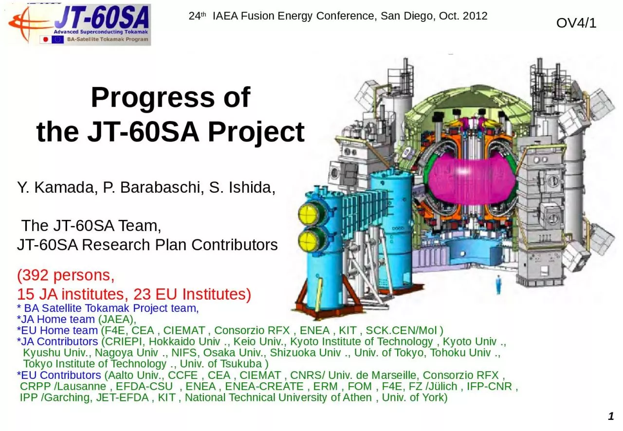
24 th IAEA Fusion Energy Conference San Diego Oct 2012 Y Kamada P Barabaschi S Ishida The JT 60SA Team JT60SA Research Plan Contributors 392 persons 15 JA institutes 23 EU Institutes ID: 811549

60sa amp demo plasma amp 60sa plasma demo univ 2012 iter high divertor control manufacture enea current heating tokamak

Share:

Link:

Embed:

Download Presentation from below link

Download The PPT/PDF document "Progress of the JT -60SA Project" is the property of its rightful owner. Permission is granted to download and print the materials on this web site for personal, non-commercial use only, and to display it on your personal computer provided you do not modify the materials and that you retain all copyright notices contained in the materials. By downloading content from our website, you accept the terms of this agreement.


Presentation Transcript

Slide1

Progress of

the JT-60SA Project

24th IAEA Fusion Energy Conference, San Diego, Oct. 2012

Y. Kamada, P. Barabaschi, S. Ishida, The JT-60SA Team,JT-60SA Research Plan Contributors

(392 persons, 15 JA institutes, 23 EU Institutes)* BA Satellite Tokamak Project team, *JA Home team (JAEA), *EU Home team (F4E, CEA , CIEMAT , Consorzio RFX , ENEA , KIT , SCK.CEN/Mol )*JA Contributors (CRIEPI, Hokkaido Univ ., Keio Univ., Kyoto Institute of Technology , Kyoto Univ ., Kyushu Univ., Nagoya Univ ., NIFS, Osaka Univ., Shizuoka Univ ., Univ. of Tokyo, Tohoku Univ ., Tokyo Institute of Technology ., Univ. of Tsukuba )*EU Contributors (Aalto Univ., CCFE , CEA , CIEMAT , CNRS/ Univ. de Marseille, Consorzio RFX , CRPP /Lausanne , EFDA-CSU , ENEA , ENEA-CREATE , ERM , FOM , F4E, FZ /Jülich , IFP-CNR , IPP /Garching, JET-EFDA , KIT , National Technical University of Athen , Univ. of York)

OV4/1

1

Slide2

JT-60SA: Highly Shaped Large Superconducting

Tokamak

JT-

60SA: highly shaped (S=q95Ip/(aBt

) ~7, A~2.5) large superconducting tokamak confining deuterium plasmas (Ip-max=5.5 MA) lasting for a duration (typically 100s) longer than the timescales characterizing the key plasma processes such as current diffusion time, with high heating power 41MW.Contribute to ‘Success of ITER’ , ‘Decision of DEMO design’ &Foster next generation leading scientists.2Sustainment Time (s)0156432

0

3000

400

JT-60SA Target

100

20

40

60

80

DEMO reactors

ITER

ITER

b

N

Existing Tokamaks

JT-60U

Steady-state

Inductive

FB ideal MHD limit

r

epresentative scenarios

5.5MA

4

.6MA

Slide3

2011

2012

Construction

Operation

Year200720082009201020132014201520162017DisassemblyAssembly

Commissioning

Preparation

2018

2019

2020

Experiment

Integrated

Commissioning

By 2012

Sep.

, 18 Procurement Arrangements (

PAs

) have been

concluded

(

JA: 10PAs, EU: 8PAs) = 75% of the total cost of BA Satellite

Tokamak

Program.

Tokamak

assembly starts in Dec. 2012, First plasma in Mar.

2019

The first experience of disassembling a radio-activated large fusion device in Japan

.

Cryostat Base

from EU

2010 Mar.

2012 Dec.

3

Careful treatment of the activated materials and safety work are being recorded as an important knowledge base for Fusion Development.

2012 Oct

.

JT

-

60U

Torus Disassembly

completed =

> JT-60SA Assembly from Dec. 2012

Slide4

4

Manufacture of

EF coils & CS: JAEA

manufacturing error (in-plane ellipticity) of the current center = 0.6mm (x 10 better than requirement

)EF5&6 manufacture started in JAEA NakaEF (NbTi) : 55%CS (Nb3Sn): 25% Conductors :under mass production (Naka)completedCS (5.1K, 8.9T) conductor test, The critical current Ic by 4,000 cycle excitation (JAEA/NIFS)=> Confirmed ‘no degradation’ Conductor Manufacture building (Naka)EF4 coil completed4.4 mCoil Manufacture building (Naka)Manufacture of EF5 & EF6 started12 m

Slide5

5

TF coil & test :

F4E, ENEA,CEA,SCK CEN

TF Conductor (F4E) under mass production.TF coil test (at nominal current): Facility preparation started(

CEA Saclay) .Cryostat (SCK CEN) ) completed & delivered to Saclay.NbTi(25.7kA,5.65T, 4.9K)Conductor Samples & Joints were tested successfully at SULTAN TF Coils (ENEA, CEA)Manufacture started:The first winding packs ~ early 2013. 6 double pancakes18 (+1 spare)ENEACEA

Slide6

1st.

2nd

3rd

Vacuum

Vessel120deg. (40deg. X 3) completedVacuum Vessel and Divertor : JAEAWelding procedure established =>tolerances well within requirement +-5mmFY2012=> another 120deg.641 MWx100s =>15 MW/m2 : W-shaped + vertical target with V-corner at the outer target & divertor pumping speed can be changed by 10 steps between 0 - 100 m3/s DivertorManufacture of brazed CFC monoblock targets on going. . The first three divertor cassettes:accuracy of 1 mm Divertor cassettes: with fully water-cooled plasma facing components & remote handlable A. Sakasai, FTP/P7-20 double wall, SS316L low cobalt (<0.05%)

Slide7

7

Cryostat Base

manufacturealmost finished

=> Delivery to Naka in the 1st week Jan.

Cryostat :CIEMAT 13.4mf ,250t Cryostat Vessel Body Cylindrical Section: drawings completed, all the material has been supplied by JAEA Cryogenic Systems :CEAQuench Protection Circuit (CNR-RFX) Prototypes completedSwitching Network Units (ENEA) Contract signed in Sep. 2012 Superconducting Magnet PS (CEA & ENEA) contracts expected by Mar. 2013 The RWM control coil PS (CNR-RFX) specification is in the final stage Power Supplies :CNR-RFX, ENEA, CEAHigh Temperature Superconducting Current Leads :KIT26 current leads based on W7-XMaterial purchasing is progressingContract of manufacture is expected within 2012 All CEA contributions: A.Becoulet, OV/4-5 P. Bayetti, FTP/P1-29

Slide8

200kV & 100s without breakdown was demonstrated with 70mm single gap.

(500

keV & 3A demonstrated in 2010)High power long pulse gyrotron (110GHz)1 MW x 70 s & 1.4 MW

x 9 s achieved with newly installed 60.3 mmf transmission line & improved mode convertor.The first dual-frequency gyrotron(110 & 138GHz) was successfully manufactured, oscillation confirmed.Development of N-NB & ECRF for JT-60SA:JAEA8N-NB System2011-: Using test stand, we found V/G0.5 ~ S-0.13 & N-0.15V: vacuum insulation voltage ( the first scaling of the multi-aperture grid)ECRF SystemMock-up test of a novel linear-motion antenna showed preferable characteristics. M.Hanada, FTP/P1-18 A. Isayama, FTP/P1-16 → 500kV extraction is expected in JT-60SA’s 3-stage-acceleration (also contributes to ITER)N: number of the apertures S: grid area (m2)G( grid length(mm))0.5V ( insulation voltage) (kV)

Slide9

9

With the ITER- and DEMO-relevant plasma parameters and the DEMO-equivalent plasma shapes, JT-60SA contributes to all the main issues of ITER and DEMO.

=> ‘simultaneous & steady-state sustainment of the key performances for DEMO’.

JT-60SA: Research GoalJT-60SA Research Plan Ver. 3.0 has been completed in Dec. 2011 with 332 co-authors (JA 145 + EU 182 + Project Team 5, from 38 institutes)

JT-60SA should decide the practically acceptable DEMO parameters, and develop & demonstrate a practical set of DEMO plasma controls. DEMO reference: ‘ economically attractive ( =compact) steady-state’but we treat ‘the DEMO regime’ as a spectrum.

Slide10

JT-60SA allows study on self regulating plasma control

with ITER & DEMO-relevant non-dimensional parameters

Collisionality

,Gyroradius,Beta,Plasma shape,First ion beta,Fast ion speed,

10PedestalCollisionalityMutual Interaction

Slide11

11

41MW×100s high power heating with variety

Variety of heating/current-drive/momentum-input combinations

Positive-ion-source NB (85keV), 12units × 2MW=24MW, CO:2u, CTR:

2u, Perp:8uNB: 34MW×100sNegative-ion-source NB, 500keV, 10MW, Off-axisECNNBN-NB driven currentTorque input138GHz2.3T110GHz,1.7TjECCD(MA/m2)EC driven currentA. Isayama, FTP/P1-16 ECRF: 7MW×100s 110GHz+138GHz, 9 Gyrotrons, 4 Launchers with movable mirror >5kHz modulation

Slide12

Profile controllability for high-

bN & high-bootstrap plasmas

12 lower N-NB

upper N-NB1.5D transport code TOPICS (with the CDBM transport model) + F3D-OFMC  Self consistent simulation for Scenario 5-1( Ip=2.3MA with ITB) By changing from the upper N-NB to the lower N-NB=> qmin increases above 1.5. S. Ide, FTP/P7-22 rToroidal rotation velocity (105 m/s)co-P-NB + ctr-P-NB+ N-NBco-P-NB + N-NB ctr-P-NB + N-NB 0.3% of VAlfvenBy changing combinations of tangential P-NBs (co, counter, and balanced) with N-NB, the toroidal rotation profile is changed significantly.  RWM-stabilizing rotationM. Honda, TH/P2-14

Slide13

13

0

1

0.5r

001327465qJT-60SA allows * dominant electron heating, (+ scan of electron heating fraction )* high power with low central fueling* high power with low external torque (+ scan)For all the representative scenarios: tflat-top(100s) > 3 x current diffusion time tRModelling studies by METIS:G. Giruzzi, TH/P2-03 Advanced inductive scenario (#4-2): q(r) reaches steady-state before t=50s with q(0)>1. ITER- & DEMO- relevant heating condition& sufficiently long sustainmentScenario 4-2 Bootstrap fraction=0.4ITER Q=10ITER S.S.

Slide14

MHD stability control

RWM

Control coil

: 18 coils. on the plasma side.

Fast Plasma Position Control coilError Field Correction (EFC) coil) bN = 4.1 (Cb =0.8) with effects of conductor sheath, noise (2G), and latency (150 ms).Stabilizing Wall(=>RMP, 18 coils 30 kAT, ~9 G~4x10⁻⁴BTRWM control14RMP+ ECCD (NTM), rotation control

Slide15

Fuel & Impurity Particle Control for ITER & DEMO

Compatibility of the

radiative divertor with impurity seeding and sufficiently high fuel purity in the core plasma should be demonstrated.

15SOL/divertor simulation code suite SONICThe separatrix density necessary to maintain the peak heat flux onto the outer

divertor target <~10MW/m2 Divertor heat flux can be managed by controlling Ar gas puffing. S. Ide, FTP/P7-22 22.53-2.8-2.4-2R (m)Z (m)nAr/niAr puffback-flow10%86420.75 pa m3/sDsep (m)qheat (MWm2)

IMPMCDetailed simulation by IMPMC illustrates dynamics of impurity:Origin (puff and back-flow) and distribution of Ar illustrated.

2

Acceptable

for #5-1:

I

p

=2.3MA, 85%

n

GW

,

separatrix

density

~ 1.6x10

19

m

-3

Slide16

Summary

The

JT-60SA device has been designed as a highly shaped large superconducting tokamak with variety of plasma

control capabilities in order to satisfy the central research needs for ITER and DEMO. Manufacture of tokamak components is in progress on schedule by JA & the EU.JT-60 torus disassembly has been completed, and JT-60SA assembly will start in Dec.2012.

JT-60SA Research Plan Ver. 3.0 was documented by >300 JA & EU researchers.In the ITER- and DEMO-relevant plasma parameter regimes, heating conditions, pulse duration, etc., JT-60SA quantifies the operation limits, plasma responses and operational margins in terms of MHD stability, plasma transport, high energy particle behaviors, pedestal structures, SOL & divertor characteristics, and Fusion Engineering.The project provides ‘simultaneous & steady-state sustainment of the key performances required for DEMO’ with integrated control scenario development.16