/
CPCPMS3001A CPCPMS3001A

CPCPMS3001A - PowerPoint Presentation

faustina-dinatale
faustina-dinatale . @faustina-dinatale
Follow
377 views
Uploaded On 2017-10-07

CPCPMS3001A - PPT Presentation

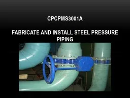
  FABRICATE AND INSTALL STEEL PRESSURE PIPING Introduction In this unit you will look at fabricating and installing steel pressure piping The unit applies to ferrous piping manufactured to AS1074 ID: 593812

systems water work pipe water systems pipe work weld system installation steel pressure steam defects high metal equipment joint

Share:

Link:

Embed:

Download Presentation from below link

Download Presentation The PPT/PDF document "CPCPMS3001A" is the property of its rightful owner. Permission is granted to download and print the materials on this web site for personal, non-commercial use only, and to display it on your personal computer provided you do not modify the materials and that you retain all copyright notices contained in the materials. By downloading content from our website, you accept the terms of this agreement.


Presentation Transcript

Slide1

CPCPMS3001A

 FABRICATE AND INSTALL STEEL PRESSURE PIPINGSlide2

Introduction

In this unit you will look at fabricating and installing steel pressure piping. The unit applies to ferrous piping manufactured to AS1074

Steel

tubes and

tubulars for ordinary service, with operating pressures not exceeding 1,750 kPa and 200°C Pipes conveying condensate, water and other liquids, fuel oil, compressed air refrigerants, Low temperature applications (including chilled water and refrigerated gases).Slide3

Frequently used terminology legend

HW

Hot water

HHW

Heating hot water

DHW

Domestic hot water

Ch W

Chilled water

Cond W

Condenser water

HT

High temperature

HP

High pressure

CWM and E

Cold water make-up and expansion tank or pipe

CI

Cast iron

MS

Mild steel

AC

Alternating current

DC

Direct currentSlide4

Typical installations

Examples of typical installations which involve the fabrication and installation of steel pressure piping systems are as follows.Chilled water systems.Condenser water systems

.

Steam and steam condensate

.Pneumatic control systems.High temperature hot water system.Refrigeration systems.Slide5

Chilled water system

Chilled water systems form part of the air conditioning systems used in larger multi storey buildings.

Chilled water is used because it is readily available, non toxic, has a high heat carrying capacity and does not require special handling considerations.

The pipe work for chilled water systems will usually be copper or steel with some installations using PVC or polyethylene.

The pipe work connects between the main

chiller

unit and the fan coil units.

Slide6

Condenser water systems

Condenser water systems are a component of an air conditioning system. Condenser water is one method of transferring heat energy from the refrigerant in the condenser of a chiller to the atmosphere via a cooling tower. Slide7

Steam and steam condensate

Steam is the vapour given off when water is boiled. Large boilers or steam generators produce steam that is used in manufacturing & also for hospitals.

Steam contains far greater heat than heating hot water

.

For example:One kilogram of 100°C water that is cooled to 50°C will give off approximately 210 kj of energyOne

kilogram of steam will give off approximately 2,500 kj of energySlide8

Steam and steam condensate

Types of steam systems include the following.Pressure system.Gravity system including a one pipe installation or a two pipe installation

.

Mechanical return system.Slide9

Water Heating & Cooling Equipment

Piping is used to convey heating & cooling mediums in air-conditioning systems.Copper , Steel & Stainless steel are the most commonly used.Steel is the most widely used for Heating & Chilled water and some sections Steam Lines

Copper is preferred for Steam Condensate Lines due to its corrosive nature .

When copper is used expansion is a high consideration, excessive movement can cause pipes to rupture.

Steel is available in many different sizes and pressure ratings , the rating of the pipe will be specified by the engineer who designs the system.There are three types produced Continuous Butt weld, Electric Resistance weld & Seamless Slide10

Pneumatic control systems

A pneumatic control system may be used for controlling heating and air conditioning equipment in large commercial and industrial applications. The system uses compressed air to supply energy for the operation of controlled devices such as:

Valves

Motors

Relays Slide11

Pneumatic control systems

Key elements of a typical pneumatic system are illustrated below. They include the following:Compressor

Air receiver

Motor

FilterPressure reducing valveController or sensorAir

main (piping) to other system components.Slide12

High temperature hot water system

High temperature, high pressure hot water refers to water heated to about 140°C at 361.4 kPa.High temperature, high pressure hot water is used as a primary heating source and can be used as the heating source for a wide range of processes including wide spread facilities like a university campus or a district heating system

.

In

these cases many buildings are spread over a wide area. Slide13

Now go to the Worksheet and answer Questions 1 – 3.Slide14

Properties of conveyed materials

The most common mediums conveyed by the previously described pressure pipe systems are: 

Component

Industrial application

Steam

Used as a heat source for industrial processes and for sterilisation in hospitals. Steam is supplied over a temperature range of 100°C to 200°C at pressures of between 100

kPa

absolute to 1,750

kPa

absolute.

Condensate

When steam is used as a heat source it is condensed back into 100

0 C hot water. This hot water is returned to the boiler and reused to produce more steam. Condensate is gravity returned to boiler using graded return or is pumped.Water – hot and coldVery widely used in heating and cooling systems, industrial processes, fire sprinkler systems and other applications. Water is supplied at temperatures varying from 3°C to 100°C. The pressure that these systems operate at will depend on the installation. For instance at ground level, the pressure in a steel pipe that is supplying water to the top of a 50 storey building will be about 2,000 kPa.OilUsed in hydraulic systems as a mechanical energy source. Oil is supplied at a wide range of pressures and temperatures depending on the applications requirements.Slide15

Properties of conveyed materials

Component

Industrial application

Refrigerants

Liquids that will vaporise into a gas thereby collecting heat from the water, air

etc with which it is in contact. Refrigeration systems have two distinct pressure sides:

the low pressure side

operatoring

at pressures from as low as -90

kPa

to as high as 1,000

kPa

and temperatures from -100°C to 30°Cthe high pressure operating at pressures up to4,000 kPa and temperatures up to 90°C.AirVery widely used for a multitude of things such as:to drive pneumatic equipmentcontrol systemsinflationvacuum systemsbreathing.Supplied over a wide range of pressures varying from negative atmospheric applications to high pressure air at pressures to 2,000 kPa and above.Slide16

Steel pipes

Steel pipes used in the fabrication and installation of the previously described systems should be in accordance with the Australian Standard Code AS1074 – 1989 Steel tubes and tubulars for ordinary service.

The wall thickness of tube applicable are designated as :

Light

MediumHeavy.Slide17

Mechanical services welding

Do not tack-weld branches in throat

All branch welds to be tack-weldedSlide18

Defects in oxy-acetylene welds

Defects may be divided into two classes:External defects, those seen on the outside of the weld area

Internal

defects, those seen when a section of the work is broken

Slide19

E

xternal defects

Undercut:

This is a groove or notch along the toe of the weld metal. It may occur continuously or intermittently, depending on the causes.

Undercut is

caused

by:

Incorrect blowpipe angle and too fast a travel rate;

Incorrect flame setting;

Poor filter rod manipulation.

It results in:

Loss parent metal strength;Formation of corrosion traps;Stress penetrations in service;Poor appearance.Slide20

E

xternal defects

Overroll

or Overlap:

This is a protrusion of weld metal past the toe of the weld or previous layer and not fused thereto.

Overroll is caused by:Too large a weld poolLoss of control of the molten metalWork wrongly positioned

Lack of manipulative ability.

It results in:

Lack of fusion between layers in multilayer welds

Stress concentrations

Waste of time and weld metal

Poor appearance.Slide21

E

xternal defects

Misalignment:

This occurs where the parts being welded have either altered their relative positions during welding or were not assembled correctly prior to welding.

Misalignment is caused by:

Poor assemblyIneffective tackingIncorrect welding sequence.

It results in:

Lack of penetration

Stress concentrations

Shearing stresses under working loads

Reduction of weld thickness.Slide22

E

xternal defects

Under and Over-sized welds:

Over-sized welds result in:

Excessive rigidity of the joint with possible overstressing of other partsExcessive heat affected zones

Waste of weld metal and timeUnder-sized welds may:Fail in service Be brittle because of rapid quenching resulting from lower heat input.Slide23

E

xternal defects

Excessive concavity:

This refers to a condition where there is insufficient metal deposited between the toes of a weld.

Excessive concavity –

The

existence of this fault would result in excessive stress concentration at the weld.Slide24

E

xternal defects

Incomplete Root Penetration:

This term is applied to the failure of the weld metal to extend into the root of a joint.

Incomplete penetration is caused by:Improper joint penetrationPoor manipulation of torch and filler rod during welding

Too large a filler rod and or too small a flame.It results in:Stress concentrations

Reduction in strength

Corrosion pockets. Slide25

E

xternal defects

Excessive penetration is caused by:

Lack of control due to small filler rod and or large flames

Incorrect joint preparation and set-up.It results in:Waste of time and weld metal

Stress concentrationsObstruction to flow in pipesExcessive heat-affected zones.

Excessive Penetration:

This fault may be identified by excess weld metal protruding through the root of a weld made from one side onlySlide26

Internal defects

Inclusions: Flux, slag and oxides may form solid non-metallic inclusions in the weld.

These cause weakened joints and may derive from:

Excessive use of flux

Overheating Poor preparationPoor manipulation.Slide27

Internal defects

(a) Gas Pores, (b) Blowholes and (c) Porosity: These are basically the same thing except that:

Gas Pores are usually spherical and less than 2mm in diameter

Blowholes are usually spherical and over 2mm in diameter

Porosity – a group of gas pores or blowholes either internal or breaking the surface of the weld.

These three may be caused by oil, grease and paint on the work surface which produce gas bubbles in the molten metal. The usual result is lowered strength and impact resistance.Slide28

Internal defects

Cold Lapping or Lack of Fusion: This fault occurs when the flames pushes liquid weld metal ahead of the pool and it adheres to metal which is below the welding temperature.

This means that the flame will probably not melt that portion of the material and fusion will not occur.

The fault may be found between the layers, where it is called cold lapping or between weld and parent metal, where it is called lack of fusion. Slide29

Joint preparation

Equal branch – Set on

Equal branch – Set inSlide30

Joint preparation

Equal Sloping Branch – Set on Slide31

Joint preparation

Un-Equal Sloping Branch – Set on Slide32

Joint preparation

Equal Sloping Branch – Set inSlide33

Joint preparation

Un-Equal Sloping Branch – Set inSlide34

Mechanical joint systems and fittings

Another method of joining steel tubes is by the use of a mechanical joining system such as victaulic couplings which are basically compression type joints.

Mechanical joints may be manipulative or non manipulative compression joints which are secured by bolting or the application of bolted flanges.

There are two main types which are .

Rolled steel pipe joint.Roll grooved type joints.

Now go to the Worksheet and answer Questions 4 – 6.Slide35

Quality assurance

Most companies these days have a policy for assuring quality to the customer. This policy is designed to control the processes used within the company, record keeping, quality of materials used and the way the work is done.

You need to be aware of your company's particular quality assurance requirements.

It is critical that the fabricator of steel pressure piping for articulated piping systems follows the manufacturers' guidelines and the pipe design engineers’ installation instructions without deviation.

This is very important with regard to the selection of components, sizing the system, fabrication details, methods of assembly, post installation testing and commissioning the system.Slide36

Plan work activities

Before you begin the fabrication and installation of steel pressure piping, you need to obtain the plans or specifications or design drawings for the job and information from the local authorities. Gathering this information will help you to make sound decisions about the nature of the job and how to plan the work process.

Some of this may be available from your job supervisor.

Before beginning any work, you may need to obtain work notices and submit them to the relevant authorities.

To plan the fabrication and installation of steel pressure piping, you need to gather information from several sources. Slide37

Source of information

The information provided

Authorities

Location of utilities such as gas, electricity, water,

stormwater

etc.

Plans or specifications

Location and details of installation.

Type of reticulated system.

Post installation testing requirements.

Company's quality assurance

Acceptable standards of workmanship clearly defined.

Quality assurance maintenance procedures.

Regulatory requirements

OH&S

Workcover

Advisory Service.

Safe working practices.

Hazardous materials requirements when using scaffolding

Hazardous locations.

Confined spaces.

Work permits.

Manufacturer's specifications

Material specifications.

Recommended installation methods and procedures.

Inspection and post inspection testing.

Sizing the complete system.

Connection with utility suppliers.

System maintenance requirements as detailed in service manuals.

System installation precautions.Slide38

Source of information

The information provided

Site inspection

Determine whether the site is a hazardous location or confined space.

Determine whether safety precautions or work permits are required.

Location of pipe installation.

Location of utility services.

Trades assistant required.

Scaffolding needed.

Before you begin the installation, it will be important for you, as the fabricator, to carefully examine the job specifications, perform a site inspection and determine the nature of any hazards present which may require a work permit or the aid of an assistant.

Your company may have procedures regarding this that you will need to take into account.

This will be particularly important if the electric arc welding process is to be used during installation.

Protection of work colleagues from arc radiation, arc flash and methods of fume extraction will need to be planned if working in a confined space.Slide39

Determine installation requirements

The plans, specifications and any working drawings must be followed while performing the work to any regulatory authority requirements. You will need to place an order for any materials required, and this must include an allowance for wastage and fabrication.

Pipe work configuration should be in accordance with the relevant regulatory authorities and should comply with the manufacturer's specifications or the pipe design engineer’s plans and specifications.

Where applicable, reference should also be made to the relevant Australian Standard codes to ensure that materials purchased or supplied comply with Australian quality standards identification markings.Slide40

Cleaning up

The work site is not just a matter of appearance, it also concerns safety and health issues. It is good work practice to clean up as you go. Building sites are always short of space and build up of debris will only add to storage, health and safety issues.

Most sites will have a site safety committee policy on cleaning up the work site.

The disposal areas for site debris should be identified at the site induction. If not find out from your supervisor.

Clean up as you go if possible, but at least on a daily and weekly basis and on completion of an installation.

Food and drink waste, wrappers and containers should be disposed of in the correct bin immediately after use as build up attracts vermin and associated health risks.

Packaging debris should not be allowed to become a tripping or other hazard. Dispose of it in the correct bin as soon as practicable.Slide41

Cleaning up

Do not use cupboards, empty rooms or corners to store rubbish and debris.

On completion of an installation check the whole of the work area. Remove materials to the store, tools and equipment to the correct location and rubbish and debris to the correct bins.

Sweep the completed work area clean and correctly dispose of sweepings.

Work site must be cleared of debris

.Slide42

Tools and equipment

must be cleaned, maintained and stored.

Keep a running check on you tool kit and your PPE. Check, clean and maintain it at the end of each day.

Check and maintain company equipment on a regular basis according to company policy.

Clean and maintain hire equipment according to hire agreement and good practice.

Do not overload or abuse any tools plant or equipment.

On completion of installation collect clean and maintain all tools and equipment.

Complete checklist and store PPE.

Complete checklist and store toolkit.

Complete checklist and store company equipment.

Complete checklist and return hire equipment.

Tools and equipmentSlide43

Hydraulic pipe bender

1. Slide

the pipe you wish to bend through the Pipe

Bender, between the Die and the Rollers. Note:

You may wish to first practice usingthe Pipe Bender on scrap material. 2. Using the slotted end of the Handle (15), tighten (clockwise) the Release Valve on the Bottle Jack


3. Insert

the Handle into the Pump Sleeve (9A) and

pump

it up and down to raise the Bottle Jack and bend the pipe. 4. When the pipe has been bent to the desired angle, remove the Handle from the Bottle Jack and use it to loosen (turn counter-clockwise) the Valve Release Screw up to one full turn. This will release the pipe from the Pipe Bender and allow you to carefully remove it.Slide44

Hydraulic pipe bender

Measurement required to

centre of Bend

Measure back the diameter of

pipe being bent

Bending Mark

Related Contents


Next Show more