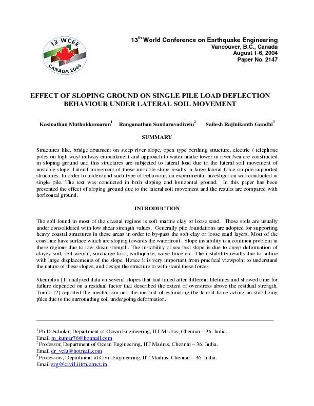
/
Fig. 5b shows the maximum bending moment variation in horizontal groun Fig. 5b shows the maximum bending moment variation in horizontal groun

Fig. 5b shows the maximum bending moment variation in horizontal groun - PDF document

faustina-dinatale
faustina-dinatale . @faustina-dinatale
Follow
418 views
Uploaded On 2016-08-03

Fig. 5b shows the maximum bending moment variation in horizontal groun - PPT Presentation

050010001500Maximum Bending Moment NmmSurcharge LoadkN 30 Relative Density 45 Relative Density 70 Relative DensityFig5a Surcharge Load Vs Maximum Bending Moment in 1V15H Sloping Ground Fig ID: 431173

050010001500Maximum Bending Moment (N-mm)Surcharge Load(kN ) 30%

Share:

Link:

Embed:

Download Presentation from below link

Download Pdf The PPT/PDF document "Fig. 5b shows the maximum bending moment..." is the property of its rightful owner. Permission is granted to download and print the materials on this web site for personal, non-commercial use only, and to display it on your personal computer provided you do not modify the materials and that you retain all copyright notices contained in the materials. By downloading content from our website, you accept the terms of this agreement.


Presentation Transcript

Fig. 5b shows the maximum bending moment variation in horizontal ground for different relative density of soil. Here the bending moment variation is almost linear with respect to surcharge load. The intensity of maximum bending moment is increasing in lesser relative density of 30% and reducing higher relative density of 70% due to increase shear strength in higher relative density. CONCLUSIONS From the experimental investigations the following major conclusions are drawn: 1) Deflection increases with increase surcharge load irrespective of ground surface and relative density of the soil. 2) The maximum deflection observed in sloping ground with low relative density of 30% and the minimum deflection observed in horizontal ground with high relative density of 70%. 3) Pile head deflection in sloping ground with 30% relative density is nearly 3 times higher than piles in horizontal ground with the same relative density. 4) Pile head deflection in sloping ground with 30% relative density is 1.5 times higher than sloping ground with 70% relative density. 5) The bending moment variation is not much significant in increasing relative density beyond 17d depth in horizontal ground. 6) The increasing relative density is not much significant in maximum bending moment occurring depth in horizontal ground, in sloping ground it is much significant. REFERENCES 1. Skempton A.W. “Long Term Stability of Clay Slopes.” 4 Ranking Lecture, Geotechnique 1969; 1412: 7-102. 2. Tomio Ito, Tamotsu Matsui. “Method to estimate lateral force acting on stabilizing pile.” Journal of Japanese Society of Soil Mechanics and Foundation Engineering 1975; 15(4): 43 – 59. 3. Towhata I, AI-Hussaini T.M. “Lateral Loads on Offshore Structure exerted by Mudflow.” Journal of Japanese Society of Soil Mechanics and Foundation Engineering 1988; 28(37): 26 – 34. 4. Mezazigh S, Levacher D. “laterally loaded piles in sand: slope effect on p-y reaction curves.” Canadian Geotechnical Journal 1998; .35: 433-441. 5. Charles W.W.Ng, Zhang L.M. “Three-Dimensional Analysis of Performance of laterally loaded sleeved piles in sloping ground.” Journal of Geotechnical and Geoenvironment Engineering. ASCE 2001; 127(6): 499-509. 050010001500Maximum Bending Moment (N-mm)Surcharge Load(kN ) 30% Relative Density 45% Relative Density 70% Relative DensityFig.5a Surcharge Load Vs Maximum Bending Moment in 1V:1.5H Sloping Ground Fig. 5a and 5b shows the maximum bending moment variation with respect to applied surcharge load on both sloping and horizontal ground. Fig. 4a corresponding to 1V:1.5H sloping ground, in which it is shown that the maximum bending moment increases with increasing surcharge load. The bending moment variation is linearly increases with increase surcharge load up to 40kN. The variation of bending moment from 40kN to 50kN surcharge load is shown nonlinear behaviour, this is due to the soil resistance beyond 40kN surcharge was reduced. It means that the soil exerts large lateral load force to the model pile. 050010001500Maximum Bending Moment (N-mm)Surcharge Load(kN ) 30% Relative Density 45% Relative Density 70% Relative DensityFig.5b Surcharge Load Vs Maximum Bending Moment in Horizontal Ground Fig.4a Bending Moment Vs Depth in Horizontal Ground Fig. 4b Bending Moment Vs Depth in for 10kN Surcharge load Horizontal Ground for 50kN Surcharge load Fig. 4c Bending Moment Vs Depth Fig. 4d Bending Moment Vs Depth 30% Relative Density 70% Relative Density -550-500-450-400-350-300-250-200-150-100-50 - 500050010001500Bending Moment (N-mm)Depth (mm ) 30% Relative Density 45% Relative Density 70% Relative Density -550-500-450-400-350-300-250-200-150-100-50-50005001000150020002500Bending Moment (N-mm)Depth (mm ) 30% Relative Density 45% Relative Density 70% Relative Density -550-500-450-400-350-300-250-200-150-100-5005001000150020002500Bending Moment (N-mm)Depth (cm) Horizontal Ground 1V:1.5H SlopingGround -550-500-450-400-350-300-250-200-150-100-50-5000500100015002000Bending Moment (N-mm)Depth (cm) 1V:1.5H SlopingGround Horizontal Ground Fig.3b Surcharge Load Vs Pile Head Deflection in 1V:1.5H Sloping Ground The maximum deflection is observed in loose state with relative density of 30% and the minimum deflection is observed in dense state with relative density of 70%. Increasing relative density will reduce the pile head deflection caused due to increase the shear strength of the soil. The pile head deflection is 66% reduced, when the ground surface changing from 1V:1.5H sloping ground to horizontal ground in 30% relative density and 71% reduced in 70% relative density. The increasing relative density with sloping ground is significantly reducing the pile head deflection. Fig. 4a and 4b shows the bending moment variation with respect to depth in horizontal ground for different relative density. Fig. 4a represents minimum load intensity of 10kN of applied surcharge load and Fig. 4b represents maximum load density of 50kN applied surcharge load. For both case the maximum bending moment occurred at a depth of 17d in 70% relative density and 14d in 30% and 45% relative density. For higher relative density which means soil in dense state the applied load transfer to deeper depth and also the mobilization of passive resistance increases, due to that the magnitude of bending moment is lesser in 70% relative density than 30% and 45%. The influence of relative density is not much significant in bending moment variation, when the pile depth beyond 17d. Fig. 4c and 4d shows the bending moment variation with respect to depth for both horizontal and 1V:1.5H sloping ground with 50kN surcharge load. Fig. 4c represents 30% relative density and Fig. 4d represents 70% relative density. Increasing relative density form 30% to 70% the bending moment variation is significantly influenced in both horizontal and sloping ground. The maximum bending moment occurred at a depth of 14d in sloping ground and 17d in horizontal ground. For sloping ground the offered passive resistance is lesser than horizontal ground due to that the maximum bending moment occurred depth is lesser in sloping ground for 30% relative density. In 70% relative density the maximum bending moment occurred at a depth of 16d in sloping ground and 17d in horizontal ground. The increasing relative density is not much significant in maximum bending moment occurring depth in horizontal ground, in sloping ground it is much significant. 0204060Surcharge load (kN)Pile head dflection(mm) 30% RelativeDensity 45% RelativeDensity 70% RelativeDensity Fig.2c Surcharge Load Vs Pile Head Deflection for 70% Relative Density Fig. 3a and 3b shows the surcharge load deflection curves of horizontal and sloping ground with different relative density. In Fig. 3a, it is shown that the deflection curve beyond 40kN surcharge load, the deflection is not much influenced by the surcharge load. The deflection is almost same for 40kN and 50kN surcharge loading; this is due to the confinement of the soil strata, while the soil surface is horizontal. In the case of sloping ground the deflection curves are different trend. Fig. 3b shows the load deflection curve of 1V:1.5H sloping ground. Here it is clearly observed that the deflected shape is linearly increasing with increasing surcharge load. This is due to the reduction of passive resistance mobilized in front of the pile. Fig.3a Surcharge Load Vs Pile Head Deflection in Horizontal Ground 0204060Surcharge load (kN)Pile head deflection (mm) HorizotalGround 1V:1.5HGround 0204060Surcharge load (kN)Pile head deflection(mm) 30% Relat i Density 45% RelatiDensity 70% RelatiDensity Fig.2a Surcharge Load Vs Pile Head Deflection for 30%Relative Density Fig.2b Surcharge Load Vs Pile Head Deflection for 45% Relative Density 0204060Surcharge load (kN)Pile head deflection (mm) HorizotalGround 1V:1.5HGround 0204060Surcharge load (kN)Pile head deflection (mm) HorizotalGround 1V:1.5HGround STRAIN METER 400 LOADING ARRANGEMENTHYDRAULIC JACKRAM HYDRAULIC PUMPTEST PILE 25mmØ PROVING RING LOADING FRAME 750 550 1300 1400 1750 175 Fig.1 Experimental Set-Up RESULTS AND DISCUSSION Fig. 2a, 2b and 2c shows the pile head deflection with respect to applied surcharge load. Fig. 2a corresponds to 30% relative density while Fig 2b and 2c corresponding to 45% and 70% relative density respectively. When surcharge load increases the pile head deflection also increases irrespective of relative density and ground condition. Form the observation it clearly shows that, in all three cases the deflection in sloping ground is much greater than deflection in horizontal ground which is due to the reduction of passive resistance mobilized in front of pile during lateral soil movement. The maximum deflection of 34mm is observed in 1V:1.5H slope with 30% relative density. The deflection for same relative density in horizontal ground is 12.5mm which is nearly 3 times higher in sloping ground. Towhata [3] investigated the important effects of submarine soil flow on offshore structures. A series of laboratory model tests were conducted to investigate the drag force which is exerted by a laminar mudflow on a vertical cylindrical column. Mezazigh [4]carried out an experimental investigation of the behaviour of piles laterally loaded at the head to study the effect of a slope on the p-y curves in dry sandy soil. The results show that the limiting distance beyond which the slope has no more influence is approximately 8B for a slope of 2 in 1 and 12 B for a slope of 3 in 2. These values are practically independent of the shear strength of the sand mass. Charles [5] investigated the performance of the sleeved and unsleeved piles constructed on a cut slope using 3D finite difference analysis. The results show that the load transfer of sleeved piles is primarily through a downward shear transfer mechanism in the vertical plane. EXPERIMENTAL TEST Test Set-Up The experimental set-up is shown in Fig 1. The test tank size is 1.3x 0.6x 1 m deep. To avoid the side friction between the tank wall and soil, two layers of plastic sheet are coated with silicon grease provided inside the tank wall. The vertical surcharge loads are applied through hydraulic jack fixed to the loading frame. The capacity of the jack is 25 T with 75 mm diameter ram; the load from the jack is applied as a surcharge load on the soil by a loading arrangement which consists of two hollow cylindrical steel pipes of 90 mm diameter, with top and bottom of steel plates of size of 450x350x10 mm. Test Pile Aluminium pipe pile having outer diameter 25 mm with wall thickness 1 mm is used as a test pile. The flexural stiffness of the pile is found by considering a simply supported beam test. The flexural stiffness of the pile is 416x10N.mm. as calculated using the center deflection of the beam. Introductory material Placement of Sand The test is conducted in river sand. The important properties of the sand are Effective particle size D10 = 0.26mm Average particle size D50 = 0.54mm Co-efficient of Uniformity Cu =2.4 Co-efficient of Curvature Cc = 1.1 Specific Gravity Gs = 2.65 Maximum Density max = 17.9 kN/mMinimum Density min = 15.3 kN/mTo achieve uniform density in the tank, a pipe and cone arrangement is fabricated. This arrangement has a hopper connected to a 940 mm long pipe and an inverted cone at bottom. The hopper has capacity of holding about 80N of sand. The sand passes through 25mm internal diameter pipe and dispersed by 60due to the inverted cone placed at bottom. The height of fall measured from the bottom of the pipe using adjustable length pointer fixed at bottom. This arrangement is calibrated by number of trails and the height of fall of 100,160 and 200mm was adopted for relative density of 30, 45 and 70% respectively. Testing procedure The test pile is embedded in both horizontal and sloping ground. The surcharge load is applied through a hydraulic jack. In sloping ground the test pile is placed in the top edge of the slope and the same location is adopted for horizontal ground also. Mechanical dial gauge is used to measure the horizontal displacement of the pile head. The bending strains are measured by using strain gauges. The lateral deformation and strain readings are recorded for each increment of loading. Professors, Department of Civil Engineering, IIT Madras, Chennai – 36. India. Email srg@civil.iitm.ernet.in Professor, Department of Ocean Engineering, IIT Madras, Chennai – 36. India. Email 13th World Conference on Earthquake Engineering Vancouver, B.C., Canada August 1-6, 2004 Paper No. 2147 EFFECT OF SLOPING GROUND ON SINGLE PILE LOAD DEFLECTION BEHAVIOUR UNDER LATERAL SOIL MOVEMENT Kasinathan Muthukkumaran Ranganathan Sundaravadivelu