/
Supplement 14B (210–VI–NEH, Supplement 14B (210–VI–NEH,

Supplement 14B (210–VI–NEH, - PDF document

faustina-dinatale
faustina-dinatale . @faustina-dinatale
Follow
409 views
Uploaded On 2016-07-28

Supplement 14B (210–VI–NEH, - PPT Presentation

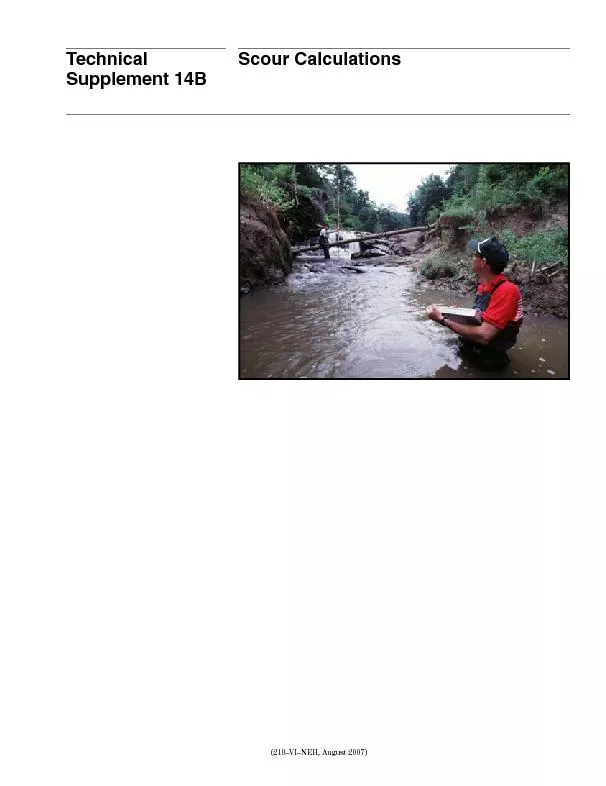
Technical Scour Calculations Part 654 National Engineering Handbook Scour Calculations Technical Supplement 14B TS14B1502210150VI150NEH summarized sonproblemsood instabilityMcCarley ID: 423357

Technical Scour Calculations Part 654 National Engineering

Share:

Link:

Embed:

Download Presentation from below link

Download Pdf The PPT/PDF document "Supplement 14B (210–VI–NEH," is the property of its rightful owner. Permission is granted to download and print the materials on this web site for personal, non-commercial use only, and to display it on your personal computer provided you do not modify the materials and that you retain all copyright notices contained in the materials. By downloading content from our website, you accept the terms of this agreement.


Presentation Transcript

Technical Supplement 14B (210–VI–NEH, Scour Calculations Part 654 National Engineering Handbook Scour Calculations Technical Supplement 14B TS14B–2(210–VI–NEH, summarized -sonproblemsood instability,(McCarley, -signaffectNEH654.09.only - ow. vertically, -centspurs,structurestheThisdepth Processes -timated Terms scour,scour, respectively,locally,temporary,ow. -tion -eralanother Table TS14B–1 Examples Date Event Stream Conditions at time of event Consequences Near-record 1989U.S. River, 1995InterstateLosLarge7Stream TS14B–3(210–VI–NEH, Part 654 National Engineering Handbook Scour Calculations Technical Supplement 14B Table TS14B–2 Streambed General process Specic process Description and subtypesAggradationAnover reachthrough ScourGeneralLongitudinallytheContractionBendBedformFormationbedforms, Dunes AntidunesLocalErosionBridgeScourchannel,Scourspan Scour at spur dike Scour at pile Scour at pile Erosion of abutment fill Exposure of footing and pile Examples Scour at pile Erosion of abutment fill Exposure of footin g Examples Part 654 National Engineering Handbook Scour Calculations Technical Supplement 14B TS14B–4(210–VI–NEH, ofdirectiontime. -ment -tionIndegradedstructuresthatcreatepoolhabitatandcover(Brookes,Knight,the below. However,Vanoni• The• Scour• Scour -tent conditions. Effects of stream types Flow regime—Streamperennial, However, ashy, Bed material and sediment transport regime —Al -luvialNEH654.01 scour, clear-wa Clear-Clear-waterow,ow, scour,clear-waterspur,pier, Clear-waterscour, clear-water Different materials scour at different rates —Non rapidly,slowly.However,slowly. TS14B–5(210–VI–NEH, Part 654 National Engineering Handbook Scour Calculations Technical Supplement 14B materialsand complexity. -sissippi Planform—Channelprocesses -nels Scour computations for design zF Sz zz zz ta dc bb fs  (eq. where: z t = totalFS = factor z = bed -sition -tion), z = contractionscour, z = scour z = bedform z s = local -calpresented supplement. Table TS14B–3 Types Type of scour or process Symbol Type of analysis z Total z clear-water z bBendBridgeNotGuidanceBedform z bfFormulasLocal z sEmpirical Part 654 National Engineering Handbook Scour Calculations Technical Supplement 14B TS14B–6(210–VI–NEH, Long-term bed elevation change however,instability,Vertical layer. layer,layer. -scribedleastby layer. Sediment inflow (volume) Change in channel volume = inflow – outflow If negative, erosion will occu r If positive, sedimentation will occur Sediment outflow (volume) Conceptual y z t D x T Flo w Before armoring After armorin g Original streambed Armored streambed Denition scour TS14B–7(210–VI–NEH, Part 654 National Engineering Handbook Scour Calculations Technical Supplement 14B zT D tx  (eq. T = thickness D = smallest x T D eP x x  1 (eq. e = porosity P = fraction -mal) Various -est x. -ing -tion DK yS S U x e g a b * (eq. y = ow S = energy S = relative 1.65 U = shear (gyS e ) 0.5 g = accelerationgravity, 2 2 ) = kinematicwater, 2/s 2 /s)K, -olds where: D = median 50, a -matedBedformula e D  0 245 0 0864 01 50 02 1 . . . . (eq. where: D 50 = median supply, new, eq.inproceedingandlimited -lustrates ex,equilibrium ad,levelForwithout Without -tinue Base level L Z ad S eq S ex Denition eq Table TS14B–4 Constants Particle Reynolds number K a B 10 68 1.67 0.67Between 27 0.86 –0.14 500 17 1.0 0.0 UD *5 0 TS14B–11(210–VI–NEH, Part 654 National Engineering Handbook Scour Calculations Technical Supplement 14B When s -cientsmust (2-b-c).formulasSimilarunder 50 5.0 -gasse S a q q n K eq s cb bc cb    10 3 22 3 3 2 (eq. K = 1.486 -rium S= S Q Q eq ex s( fu tu re ) s( existing ) 10 3b -c  (eq. where: S = existing Q = sedimentsupply, 3/s 3 /s)The -ment Beds coarser than sand—no sediment supplied from upstreamentirely. Variable • Simultaneous 50 SD S K qn eq cc g Q$ 10 7 6 7 (eq.• BasedMeyer-Peter sand: SK Dn Dq eq 50 10 7 9 7 90 5 14 6 7 (eq.• Based SK D q eq m 3 4 (eq.• Based SK QD eq d 04 6 50 11 5 .. (eq. Table TS14B–6 RangesYang Quantity Range (SI units) D 50, velocity,y, 0.00005–0.002Manning n 0.015–0.045Froude water, 3/s 3 /s)4.0–200 Part 654 National Engineering Handbook Scour Calculations Technical Supplement 14B TS14B–12(210–VI–NEH, K = constants S = equilibrium c move S = relative q = channel-forming 3 /s/ft 3 /s/m) = Manning’s D = sedimentner, D = median Note units ) D m = mean Q = design 3/s 3 /s) Q = discharge 3/s 3/s).Normally d /Q y = mean n b = Manning’s Sediment continuity analysistheory, -ity VV V ss in out  (eq. Table TS14B–7 Constants Relationship U.S. units SI units ReferenceManning 1.486 Meyer-Peter 60.1 28.0Lagasse, Schoklitsch 0.00174 0.000293Pemberton Henderson0.44 50 0.33 50 Henderson where: V = volume 3 3 ) V s = volume 3 3 ) V s = volume 3 3 )From z V WL ad cr (eq. where: W = average L = reachValues s YangNormally, -puted discharge. V.Alternatively, -sign TS14B–13(210–VI–NEH, Part 654 National Engineering Handbook Scour Calculations Technical Supplement 14B n discrete VtheNumerical V VV Vt i n si si i in out   1 (eq. More complex approaches for long-term aggradation or degradation ow. other,scour. capacity.BRI–STARS STARS• channel• structure• hydraulic• geologic• downstream• event• tributary• bed-material• upstream• tributary• selection • depth -calpredict -tion (1993c). General scour Process descriptioncommonly,necessarily,scour.Presumably,scour. zm ean KD t  50 0 115 . (eq. and zK D t ma x .  50 0 115 (eq. Part 654 National Engineering Handbook Scour Calculations Technical Supplement 14B TS14B–14(210–VI–NEH, where: (mean) = best z t (max) = enveloping K = coefcient t z t max,units), 50 bedPembertonequationscould -nels.formulas, value.These zK QW D td a f bc 50 (eq. where: z t = maximum K = coefcient Q = design 3/s 3 /s) W = ow D = medianc = exponentsValues d , and W f Values f, 50 -limeters continuity, -esisvelocityincontractedout Table TS14B–8 Constants 50 Condition Lacey Blench K a b c K a b cStraight 0.097 1/3 0 –1/6 0.530 2/3 –2/3 –0.1092Moderate 0.195 1/3 0 –1/6 0.530 2/3 –2/3 –0.1092Severe 0.292 1/3 0 –1/6 0.530 2/3 –2/3 –0.1092Right 0.389 1/3 0 –1/6 1.105 2/3 –2/3 Vertical 0.487 1/3 0 –1/6 Condition Lacey BlenchStraight 0.030 0.162Moderate 0.059 0.162Severe 0.089 0.162Right 0.119 Vertical 0.148 0.000 Table TS14B–9 Constant 50 TS14B–15(210–VI–NEH, Part 654 National Engineering Handbook Scour Calculations Technical Supplement 14B formfrom Live-bed contraction scourLive-bed c,of clear-water VK yD c 1 6 50 1 3 (eq. where: V = criticalvelocity,y = average (m) D = medianK = a -ing zy y co  2 (eq. and y y Q Q W W b b a 2 1 2 1 6 7 1 2 (eq. where: z = contraction y = average y = average y = average - tion Q 1 = ow 3/s 3 /s) Q 2 = ow 3/s 3 /s) W b1 = bottom W = bottoma = empirical -mined Table TS14B–10 Exponent U * / a Mode of bed-material transport 0.59Mostly0.50 0.64Some 2.0 0.69Mostly Ug yS e * 1 2 1 1 2 where: U * = ( o / ) 1/2 1 S e ) g = accelerationgravity, 2, 2 ) S e = slope = average 2 2), TG oe RS where: R = hydraulic S e = energy U = densitywater, 3 3 ) Z = fall 50, Part 654 National Engineering Handbook Scour Calculations Technical Supplement 14B TS14B–16(210–VI–NEH, Fallthe (2000).  KS gD KS gD gs gs 1 2 2 (eq. where: KA A 1 05 9 0 055 12 0 0004  .t an he xp . . (eq. KA A 2 05 0 10 60 016 120 .t an h. ex p . (eq. S g = relative g = accelerationgravity, 2 2 ) = kinematicwater, 2 /s 2 /s) D s = adiameter, A Sg D gs 3 2 (eq. b1 b2,use o may layer. clear-water Wallerstein - nuity. 0.01 0.10 1.0 0.001 0.01 0.1 1.0 (ft/s) (m/s) D S (mm) D S (m) 10 T = 0º C 20º C 40º C 0.01 0.001 0.0001 0.1 1.0 0.01 Fall Part 654 National Engineering Handbook Scour Calculations Technical Supplement 14B TS14B–18(210–VI–NEH, Briey, scour, b y mean – max . zy y y b  ma x 1 (eq. y = average y = maximum y y W Rc i ma x ..  15 45 (eq. where: W = channelRc = bend max /y mean topography.upper-bound max /y mean ranges i /Rcbetween i /Rc0.56, max recommended max /y mean.ConsultRelationsdepth -tionship L R R p 0 0604 1 6 . n (eq. where: L = recommended R = hydraulicperimeter, = Manning n This -siderably River.scour.Hebler, 1998): y y FS Rc W W y ci i c ma x .. .  18 0 051 0 0084 (eq. where: y = maximum y c = meanFS = a Rc/W 1 1 /y safety, max /y c by -cent max /y c scour. y max /ycpredictedthan 1bend TS14B–19(210–VI–NEH, Part 654 National Engineering Handbook Scour Calculations Technical Supplement 14B Bedform scour Process descriptionscour, ow. scour.however, -tations Bedform predictorsWater Van DD Sg g * 50 2 1 3 10 (eq. and 31 5  T ts (eq. where: T ts sc c TT (eq. Region of high shear stres s R c L p Fl ow Denition p 0.05 0.1 0.5 0.01 1.0 5.0 10.0 50.0 n L p /R R=10.0 R=5.0 R=0.5 R=1.0 R=0.1 L R R n p 0 0604 1 6 . Recommended p/R,function -cient n,radius, Part 654 National Engineering Handbook Scour Calculations Technical Supplement 14B TS14B–20(210–VI–NEH, W ater surface Plane bed Ripples Dune sT ransition Plane bed Standing waves and antidunes Bed Lower regime T ransition Stream power Bedform Upper regime Upper flow regim e Lower flow regime A=2z b A=2z b Resistance to flow (Manning’ s roughness coefficient) Relative D = dimensionless D = mediang = accelerationgravity, 2 2 ) Q water, 2/s 2 /s) T = dimensionless s * = bed lb/ft 2 2), s gu R D 2 90 2 18 12 3 lo g (eq. u = meanvelocity,R = hydraulic D = size c * = critical c * = D 50 50 c * 2 ( c *=16,187 D 50 50 c * 2 ) where: = dimensionless -gomery c D D   02 4 0 055 10 02 . .e xp . * (eq. where: DD g * . 50 2 1 3 16 5 (eq. where: D = dimensionless D 50 = mediang = accelerationgravity, 2 2 ) Q water, 2/s 2 /s) TS14B–21(210–VI–NEH, Part 654 National Engineering Handbook Scour Calculations Technical Supplement 14B Transitional ts antidunes occur, viscosity,geometry.occur, $ 01 11 05 25 50 03 07 .e xp . .. Dy TT ts ts where: = duney = mean -mator maximum or z bf 2 scour. Yang Scour associated with structures Structures that span the full width of the channel -atedwsconstruction later. Scour (a) (b) Part 654 National Engineering Handbook Scour Calculations Technical Supplement 14B TS14B–22(210–VI–NEH, Predictinggrade Commonly, -mulas, SillsSeries -quent -mulas 0.02)(S Fors(g.TS14B–16), z H a SD s sg 0 180 0 369 1 50 .. (eq. p tests l H a SD p sg 18 74 02 1 50 .. (eq. s z H a H a SD s ss g  0 4359 1 4525 0 0599 1 0 8626 1 95 14 .. . . . 9 908 Denition L s Z s Bed surface after scour S o S eq p l and l H a H a SD p ss g  4 479 0 023 2 524 1 1 808 1 95 1 129 .. . . . where: z s = depth H = specic H q g s s 15 2 3 . (eq. where: q = ow 3/s/ft 3 g = accelerationgravity, 2 m/s 2 ) a 1 = the aS SL oe qs 1   where: S = initial L = horizontal (m) S = equilibriumscour, which S SD y eq cg Q$ 50 (eq. TS14B–27(210–VI–NEH, Part 654 National Engineering Handbook Scour Calculations Technical Supplement 14B The -ies /y. c/y =for c/y c/y K 2 = dimensionless ow K = 17.106 2 for (45 o o b = dimensionless 1 -ed c/y K 1 1 2 07 51 2  . ta n ta n (eq. where: = angle = side -tiveThe Table Part 654 National Engineering Handbook Scour Calculations Technical Supplement 14B TS14B–28(210–VI–NEH, Table TS14B–11 Summary Predominant bed material Type of analysis Long-term bed elevation change General scour Local scour All types of scour Armoring analysis Equilibrium slope Contraction scour Bend scour Bedform scour Bridge pier and abutment scour Structures that span the channel Structures that do not fully span the channel Numerical modelingClay cohesive X Regionalregressions O O X O O O O Sand X Nomaterial supply—(12) Reductionsediment (13) Eliminationofsediment (7) Empirical (21–23) Dunes (43–44) Antidunes(43, (2001) Vertical drops Rampssloping (63–64) (65, Live-bed conditions (25–26) Clear-water conditions (31–32) (33–36)Fine (2–4) Gravel cobble (14–17) X X Sills(45, O Boulders O O O X X O Step-pool structures (51) O O occur,uncertainty. TS14B–29(210–VI–NEH, Part 654 National Engineering Handbook Scour Calculations Technical Supplement 14B Example computations Sand-bed reach - Given : 1,000 3 1.94 3solids 2,630 5.10 density, 1.63 constantManning’s equation 0.034Shields 0.038215 0.038215 mm 0.009 D mm 0.005 D mm 0.003 D mm 0.003 D mm 0.001 D mm 0.0010m 6,562Manning’s 0.027 (1/3)design d 392.2 /s 13849 3 velocity,m/s 7.1 /s/m 70 3 yr, 25 30 /s/m 0.86 3 m/m 0.0008 Rc m 3,2812H:1V, Part 654 National Engineering Handbook Scour Calculations Technical Supplement 14B TS14B–30(210–VI–NEH, Find Total a. Compute DK yS S U x e g a b * U e ) 0.5Assumee= o U * .. .. s s 32 29 80 0008 05 0 ft/ s Particle Re .. . *  UD 50 5 05 00 001 10 51 0 48 Therefore, D x 27 98 0 0008 16 3 05 0 10 51 0 00 08 6 5 01 4 .. . . . . .. 6 6 18 ft mm layer. Compute a. UsingYang -pute TS14B–11). an D D  0 025 00 7 0 025 0 027 23 90 8 50 01 4 23 90 50 .. .. .. lo g . .. .l og . .. . 80 14 6 50 03 00 7 12 11 0 D  s bD    49 30 74 49 30 74 03 53 2 50 .. lo g .. lo g. . cD     04 60 65 04 60 65 03 08 0 50 .. lo g .. lo g. . qa uy s bc q s s    12 11 07 19 80 0066 6 53 20 80 .. .. .. ft /s 2 b. Compute S a q q n K eq s cb bc cb    10 3 22 3 3 2 S eq 12 11 0 0 066 70 0 027 1 486 00 0 6 05 4 08 9 2 . . . . . . . 0 083 Since -matelyequaltotheequilibriumslope,long-termdegradation Computescour.a. Check TS14B–24. VK yD c 1 6 50 1 3 V c   11 17 98 0 001 16 0 1 6 1 3 .. .. ft/ s Since occur.b. Compute A Sg D gs 3 2 A ss   16 33 22 0 001 10 51 0 500 3 5 2 .. . . KA A 1 05 9 0 055 12 0 0004  .t an he xp . . K 1 05 9 0 055 12 500 0 0004 500 0 014   .t an he xp .. . KA A 2 05 0 10 60 016 120 .t an h. ex p . K 2 05 0 10 60 016 500 120 500 0 291  .t an h. ex p. .  KS gD KS gD gs gs 1 2 2 TS14B–31(210–VI–NEH, Part 654 National Engineering Handbook Scour Calculations Technical Supplement 14B W ss    ss 0 014 16 33 22 0 001 10 51 0 0 291 16 33 22 00 0 2 5 .. .. . .. .. 1 10 135 . ft/ s Compute K 1 1 2 07 51 2  . ta n ta n K 1 1 2 07 51 24 5 27 03 4    . ta n ta n . z y K L y sc a 1 since z y s 03 4 65 6 98 08 8 05 . . . . . zy s s 08 8 08 89 8 86 . .. . ft Compute zF Sz zz zz ta dc bb fs  z t  13 03 20 08 61 54 .. .. ft Compare TS14B–21. zK D t ma x . 50 0 115 z t ma x. .. .  65 0 001 14 4 0 115 ft The Values t smaller, respectively.c. Compute * / U * .. .. s s 32 29 80 0008 05 0 ft/ s U * . . .  05 0 0 135 37 2 ft/ s d. Using * / e. Compute 2 with y 1 0 ft, 1 2 . y y Q Q W W b b a 2 1 2 1 6 7 1 2 y 2 06 9 98 60 40 13 2 . . . y zy y co 2 2 13 29 81 30 13 09 83 2 s   .. . .. . ft ft Computescour. DD Sg g * 50 2 1 3 10 D * . .. . .   0 001 16 33 22 10 51 0 78 10 5 2 1 3 Dunes Part 654 National Engineering Handbook Scour Calculations Technical Supplement 14B TS14B–32(210–VI–NEH, Gravel-bed reach Given density, g c 0.056 0.055653 grain s mm 0.287 D 95 mm 0.574 D 90 650.213 D 84 250.082 D mean 150.049 D 50 m 6,562 ’s n 0.030 (1/3) 0.030 (1/3)design d 40.5 /s 1,430 3 velocity, /s/m 24 3 m/m 0.0024 m 3,281 w 0.31.0weir w surface 0.5 d 0.72.3angle00.0 TS14B–33(210–VI–NEH, Part 654 National Engineering Handbook Scour Calculations Technical Supplement 14B Total Compute a. Compute x using DK yS S U x e g a b * U * e )0.5. e o U * ... . s s 32 23 90 0024 05 5 ft/ s Particle Re .. . , *  UD 50 5 05 50 043 10 51 0 2 252 Therefore, D x  17 39 0 0024 16 3 0 0976 30 .. . . ft mm Particlesb. ComputeT, T D eP x x  1 where e D    0 245 0 0864 01 0 245 0 0864 01 13 0 327 50 02 10 21 . . . . . . . .. since 84 a = T   0 0976 10 327 01 6 09 1 . .. . ft c. Compute x . zT D xx   09 10 098 08 1 .. . ft Compute a. Manning SD S K qn eq cc g Q$ 10 7 6 7 c 50 S eq s 0 056 0 043 16 3 1 486 24 00 3 0 00068 10 7 6 7 .. . . . . b. Meyer-Peter SK Dn Dq eq 50 10 7 9 7 90 5 14 6 7 S eq   60 1 0 043 00 3 0 065 24 0 0013 10 7 9 7 5 14 6 7 . .( .) .( ) . c. Schoklitsch SK D q eq m 3 4 S eq 0 00174 15 24 0 0012 3 4 .. d. Henderson SK QD eq d 04 6 50 11 5 .. S eq   04 41 430 0 043 0 00042 04 61 15 ., .. .. e. Compute eq values zL SS ad ex eq   z ad  6 562 0 0024 0 0011 85 ,. .. ft Since Part 654 National Engineering Handbook Scour Calculations Technical Supplement 14B TS14B–34(210–VI–NEH, Computea. UsingVeronese yz Kh q sd  0 225 05 4 .. yz s   13 21 62 38 2 0 225 05 4 .( .) . . . ft zy s   82 82 39 43 . .. . ft b. Using zK qh y gD s a d b t m 01 5 03 00 10 . .. z s      34 22 05 07 98 02 5 27 06 01 50 15 03 00 10 . .. . .. . .. . .. m c. Using A Q Wy gD S d ww g 50 50 A 50 1 430 49 21 03 22 0 043 16 3 19 3   ss , .. .. . . z s  27 89 .. m ft Compute zF Sz zz zz ta dc bb fs  Use z t  13 08 00 00 00 89 12 6 .. .. .. . ft Compare zK D t ma x .  50 0 115 z t ma x. .. .  65 0 043 93 0 115 ft Blodgett’s respectively.However, t Blodgett’s z y W y y h A D D s w w w t d 0 540 0 593 0 126 50 0 544 90 50 . . . . 0 856 0 751 . . W W w z y s w 0 540 15 03 07 05 19 3 02 0 593 0 126 0 544 . . . . (. ) . .. . 1 13 0 043 49 2 62 79 6 0 856 0 751 . . . .. zm s  s 79 67 96 03 24 .. .. y w Estimate TS14B–35(210–VI–NEH, Part 654 National Engineering Handbook Scour Calculations Technical Supplement 14B Design features and measures to address scour -theroftwoways(g.TS14B–22(USACE1991b)).Theymay Watson Alternatively,However, Four Z t Method A T Method CM ethod D c=5T T T i=1.5T Low water Method B T Key-in to prevent sliding Rock L y As-built Launched Scour Part 654 National Engineering Handbook Scour Calculations Technical Supplement 14B TS14B–36(210–VI–NEH, 1V:2H r,where r (m), VT z st one rt 33 5 . (eq. where: V stone = additional 3/ft 3 /m) z = total Variations -es With scour, -proach TS14B–37(210–VI–NEH, Part 654 National Engineering Handbook Scour Calculations Technical Supplement 14B List of symbols a = morphological o eq )Lsft = dune D = dimensionless D = median D = size D = size D = the D = diameter (m) D = mean (m) D = adiameter, S = change 1.65 V = change 3 3 e = porosity = angleFS = factorg = accelerationgravity, 2 2 ) = specic 3 (N/m 3 ) = specicwater, 3 3 ) h = height h = verticalweir, H = specic = side L = reach L = length L = recommended L = horizontal l = length L max = horizontal (m) n = Manning ’s Q water, 2/s 2 /s) P = the q = channel-forming 3/s/ft 3 /s/m) = dimensionless = critical Q = design 3/s 3 /s) Q = sedimentsupply, 3/s 3 /s) q = sediment 2/s (m 2 /s) = Densitywater, 3 3 R = hydraulicRc = bendS = average S = energy S Slope S = energy eq S = equilibrium c no S = existing S = specicT = thickness (m) = critical 2 2 ) c = critical 2 2 ) = average 2 2 ) T = thickness s = bed 2 2 ) T = dimensionlessu = meanvelocity, U = shear e ) 0.5 Part 654 National Engineering Handbook Scour Calculations Technical Supplement 14B TS14B–38(210–VI–NEH, V = criticalvelocity, V = additional 3/ft 3 /m) V = volume 3 3 ) Vs = volume 3 3 ) Vs = volume 3 3 W = average Z  D W = ow W = bottom (m) W = bottom W = average W = ow W = channel (m) W = widthy = ow y = mean y = maximum y = tailwater y = vertical z = bed z = scour z = bedform z = clear-waterscour, z = depth z = local z = total