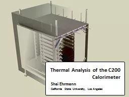
Shai Ehrmann California State University Los Angeles Tasks Accomplished July August Prepared and repaired 250 PMTs for GRINCH Removed 50 PMTs for HCAL from Big HAND Measured flatness of ID: 525737
Download Presentation The PPT/PDF document "Thermal Analysis of the C200 Calorimeter" is the property of its rightful owner. Permission is granted to download and print the materials on this web site for personal, non-commercial use only, and to display it on your personal computer provided you do not modify the materials and that you retain all copyright notices contained in the materials. By downloading content from our website, you accept the terms of this agreement.
Slide1
Thermal Analysis of the C200 Calorimeter
Shai Ehrmann
California State University, Los AngelesSlide2
Tasks Accomplished July - August
Prepared and repaired 250 PMTs for GRINCHRemoved 50 PMTs for HCAL from Big HANDMeasured flatness of
HCAL scintillator sampleStudied 100 light guides for ECAL by measuring flatness and perpendicularityConducted experimental study of thermal conductance and cooling of light guides Calculated thermal properties of ECALTemperature gradientsHeating and cooling timesResearched heat induced transparency loss
Conducted thermal annealing experiments Began 3D thermal analysis of ECALPrepared input filesAssisted
Silviu
Covrig with ANSYS analysis
2Slide3
What is the C200 calorimeter?
Designed to maintain permanent heat annealing to lead glass blocks.
3Slide4
What is the C200 calorimeter?
Designed to maintain permanent
heat annealing to lead glass blocks.Calorimeter receives heat from several heaters to ideally maintain a 1-dimensional linear temperature gradient. The entire system is insulated on all sides.
4Slide5
What is the C200 calorimeter?
Designed to maintain permanent
heat annealing to lead glass blocks.Calorimeter receives heat from several heaters to ideally maintain a 1-dimensional linear temperature gradient. The entire system is insulated on all
sides.
Calorimeter is comprised of lead glass blocks attached to light guides, which
provide a cooling
temperature gradient for proper PMT functioning.
*Q(A) and Q(B) denote the desired direction of heat flux
5Slide6
What is the C200 calorimeter?
Designed to maintain permanent
heat annealing to lead glass blocks.Calorimeter receives heat from several heaters to ideally maintain a 1-dimensional linear temperature gradient. The entire system is insulated on all
sides.
Calorimeter is comprised of lead glass blocks attached to light guides, which
provide a cooling
temperature gradient for proper PMT
functioning.
Lead glass blocks are organized in a 20x20 array, while light guides are organized in
a skewed
10x20
array.
6Slide7
Primary Heat Analysis
Thermal analysis is essential to ensure design feasibility and efficiency.
7Slide8
Primary Heat Analysis
Thermal analysis is essential to ensure design feasibility and efficiency.
Heat is provided from a main heater to achieve Q(A) and from an auxiliary heater to achieve Q(B), which together administer an appropriate temperature gradient throughout the system.
8Slide9
Primary Heat Analysis
Thermal analysis is essential to ensure design feasibility and efficiency.
Heat is provided from a main heater to achieve Q(A) and from an auxiliary heater to achieve Q(B), which together administer an appropriate temperature gradient throughout the system.
Primary heat analysis shows that the regime requires a net power of 156 W.
Desired Temperatures
:
Surface A →
225
°C
Surface B →
175
°C
Surface C → 50 °C
Corresponding Heat Required:
9Slide10
Light Guide Temperature Gradient Study
Goal: to test cooling at PMT and to study heat transfer in the light guide.
10
*Light guide with approximately 2 cm of wool glass insulationSlide11
Light Guide Temperature Gradient Study
Goal: to test cooling at PMT and to study heat transfer in the light guide.
We attach a copper radiator to amplify cooling effect.
*
The copper radiator acts as a heat exchanger to ensure and maintain appropriate temperature at cool end.
11Slide12
Light Guide Temperature Gradient Study
Goal: to test cooling at PMT and to study heat transfer in the light guide.
We attach a copper radiator to amplify cooling effect.
Results verify the efficacy of a copper radiator in cooling; as T1 approached 200 ᵒC, T3 remained below
40
ᵒC.
T1
T2
T3
12Slide13
Heat up and cool down
For experiment logistics and safety we assess the amount of time necessary to heat up the C200 calorimeter and the effects of cool down.
13Slide14
Heat up and cool down
For experiment logistics and safety we assess the amount of time necessary to heat up the C200 calorimeter and the effects of cool down.
Solving the heat equation for the specific thermal system, we find that the regime of lead glass heating will ideally achieve a thermal gradient within 1% of equilibrium in 75 hours, within 5% in 40 hours, and within 10% in 30 hours.
14
Lead Glass
Time-Based Temperature Profile
225 ᵒC
175
ᵒC
Initial Profile
10 hours, 50% Equilibrium
30 hours, 90% Equilibrium
40 hours, 95% Equilibrium
75 hours, 99% EquilibriumSlide15
Heat up and cool down
Cool down in the case of immediate shut off will primarily occur by convection and conduction through the light guides due to low thermal conductivity in foam glass insulation.
15
Lead Glass
Light Guide
Foam Glass Insulation
Slide16
Heat up and cool down
Cool down in the case of
immediate shut off will primarily occur by convection and conduction through the light guides due to low thermal conductivity in foam glass insulation. Analysis shows that the temperature gradient in the calorimeter will reach approximately 10 ᵒC/cm at the onset of cooling and will relax until reaching room temperature.
16
Lead Glass
Light Guide
225
ᵒC
175ᵒC
50ᵒC
10 ᵒC/cmSlide17
Expansion Cycles
Steel bracing will expand more rapidly and with greater magnitude than lead glass during heat up.
17Slide18
Expansion Cycles
Steel bracing will expand more rapidly and with greater magnitude than lead glass during heat up.
Expansion is relatively minimal, and should not compromise the mechanical integrity of the calorimeter.18
∆L = 0.15 mm
∆L = 1 mmSlide19
Expansion Cycles
Steel bracing will expand more rapidly and with greater magnitude than lead glass during heat up.
Expansion is relatively minimal, and should not compromise the mechanical integrity of the calorimeter.
The effective linear thermal expansion between the surfaces of lead glass and the surfaces of steel bracing will create a gap of 1.4 mm on the sides and 3 mm on the top. These gaps will be mediated with spring bracing to maintain compression on the lead glass array.
19
∆L = 3 mm
∆L = 1.4 mmSlide20
Expansion Cycles
Steel bracing will expand more rapidly and with greater magnitude than lead glass during heat up.
Expansion is relatively minimal, and should not compromise the mechanical integrity of the calorimeter.
The effective linear thermal expansion between the surfaces of lead glass and the surfaces of steel bracing will create a gap of 1.4 mm on the sides and 3 mm on the top. These gaps will be mediated with spring bracing to maintain compression on the lead glass array.
During the cooling cycle,
steel will
contract more rapidly. The peripheral blocks of lead glass will contract more quickly
than the inner blocks and leave small gaps due to shrinking.
20Slide21
Lead Glass Annealing
Goal: to study the relationship between annealing time, temperature and effectiveness in reducing radiation damage.
21Slide22
Lead Glass Annealing
Goal: to study the relationship between annealing time, temperature and effectiveness in reducing radiation damage.
Data was taken for lead glass blocks at various durations and temperatures of heat soaking to measure the magnitude of damage reduction. Results verify that annealing temperature and annealing duration are both important factors in eliminating radiation damage.
22
Block
Temperature
Duration
Damage Reduction Factor
[ ᵒC]
[Hours]
A
200
4
11.22
B
200
2
3.60
C
250
4
66.72
D
225
2
25.23
E
225
8
58.50Slide23
Lead Glass Annealing
Goal: to study the relationship between annealing time, temperature and effectiveness in reducing radiation damage.
Data was taken for lead glass blocks at various durations and temperatures of heat soaking to measure the magnitude of damage reduction. Results verify that annealing temperature and annealing duration are both important factors in eliminating radiation damage.
Several blocks were re-annealed in order to attain maximum transparency. Results showed that blocks do not have the same base absorption.
23
Re-anneal
Data
Block
Temperature
Duration
Base
Absorption
[µA]
[ ᵒC]
[Hours]
C
225
12
~ 0.5
D
250
12
~ 0.7
E
250
16
~ 0.75
225
12Slide24
Conclusion
24
The study of thermal annealing of lead glass blocks allows us to quantify the radiation damage reduction.Slide25
Conclusion
25
The study of thermal annealing of lead glass blocks allows us to quantify the radiation damage reduction.During heating and cooling cycles, the C200 design maintains mechanical stability.Slide26
Conclusion
26
The study of thermal annealing of lead glass blocks allows us to quantify the radiation damage reduction.During heating and cooling cycles, the C200 design maintains mechanical stability.
The net heat loss through insulation is approximated at 225 W; however the real heat loss will be much greater due to insulation gaps and bracing design. We can thus estimate that the heaters should generate at least 1 kW.Slide27
Conclusion
27
The study of thermal annealing of lead glass blocks allows us to quantify the radiation damage reduction.During heating and cooling cycles, the C200 design maintains mechanical stability.
The net heat loss through insulation is approximated at 225 W; however the real heat loss will be much greater due to insulation gaps and bracing design. We can thus estimate that the heaters should generate at least 1 kW.
The light guides measured for flatness and perpendicularity are of adequate quality to allow for proper attachment to lead glass and to
PMTs.