/
Photoelectric Photoelectric

Photoelectric - PDF document

giovanna-bartolotta
giovanna-bartolotta . @giovanna-bartolotta
Follow
405 views
Uploaded On 2016-07-09

Photoelectric - PPT Presentation

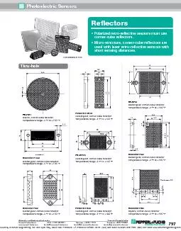
wwwfargocontrolscom 732 3893376 Fax 732 5423553 49 18 mm Stainless Steel DCFEATURES Stainless steel housing Programmable output NPNPNP Sensitivity adjustment standard LED function indica ID: 396688

www.fargocontrols.com 732 389-3376 Fax

Share:

Link:

Embed:

Download Presentation from below link

Download Pdf The PPT/PDF document "Photoelectric" is the property of its rightful owner. Permission is granted to download and print the materials on this web site for personal, non-commercial use only, and to display it on your personal computer provided you do not modify the materials and that you retain all copyright notices contained in the materials. By downloading content from our website, you accept the terms of this agreement.


Presentation Transcript

Photoelectric www.fargocontrols.com 732 389-3376 Fax 732 542-3553 49 18 mm Stainless Steel, DCFEATURES: Stainless steel housing Programmable output NPN/PNP Sensitivity adjustment standard LED function indicators Short circuit & reverse polarity protection Pre-wired cable or connector models Compliant to the EMC directive Protection degree IP67: dust tight and protection from the Type Direct Reflection Reflection with tion with reflectorThru Beam Receiver Emitter Cable, PVC, L= 2m S4050 Connector C S4051 S4055 S4061 S4071 S4083 S4081 Add 5 mm to length for connector models Optional 90 beam available upon Operating Distance 20 cm* 250 cm** 1500 cm External Diameter M18 x 1 Light Source Infrared Programmable Output NPN/PNP NO + NC Power Supply 10 – 30 Vdc Power on Delay Power Drain 50 mA 20 mA 35 mA Voltage Drop (on state) 3 V _ Switching Current (max) _ Short Circuit Protection Yes _ Operating Frequency 700 Hz max Light Immunity � 10,000 Lux Case Stainless steel AISI 303 Protection Degree IP 67 Operating Temperature Storage - 20 to +90 Working - 20 to +50 * The operating distance is related to matt white paper dim. 10 x 10 cm. ** The operating distance is related to CT80 reflecto INSTRUCTIONS FOR THE PROGRAMMING AND ADJUSTMENT TRIMMER FOR THE SENSING RANGE ADJUSTMENT: The photocell is supplied with max sensing range with the trimmer totally rotated in the clockwise direction. The sensitivity reduces by rotating the trimmer in the counterclockwise direction. SWITCH NPN/PNP: The photocell is supplied with the switch in P (PNP output). To change to NPN turn the switch to N in the counterclockwise direction. WARNING! Do not carry out the switching when the photocell is powered. GREEN LED - STABILITY INDICATOR: This LED is on when the level of the output signal and the alignment of the photoelectric sensors are in the optimum position. In the case, that the LED is off, this indicates that the lens is obscured. For the types with direct reflection, a possible alteration of the dimension or color may cause the LED to go off. YELLOW LED - OPERATION INDICATOR: This LED is on when the object to be detected enters the sensing range of the photocell giving output signals. NOTE! Program the photo cell to NPN or PNP function before applying power NOTE! It is recommended that the proper tool be used to rotate the trimmer and the switch to avoid damage