/
U-boat Radio Room Personnel - Equipment - Procedures U-boat Radio Room Personnel - Equipment - Procedures

U-boat Radio Room Personnel - Equipment - Procedures - PowerPoint Presentation

giovanna-bartolotta
giovanna-bartolotta . @giovanna-bartolotta
Follow
344 views
Uploaded On 2019-11-20

U-boat Radio Room Personnel - Equipment - Procedures - PPT Presentation

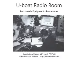
Uboat Radio Room Personnel Equipment Procedures Captain Jerry Mason USN ret VE7YAB Uboat Archive Website http uboatarchivenet Oberfunkmaat Georg Seitz 17 years old tobacco farmer to radioman in 17 months ID: 766131

khz mhz radio telefunken mhz khz telefunken radio power wave room receiver boat frequency rec broadcast circuits high size

Share:

Link:

Embed:

Download Presentation from below link

Download Presentation The PPT/PDF document "U-boat Radio Room Personnel - Equipment ..." is the property of its rightful owner. Permission is granted to download and print the materials on this web site for personal, non-commercial use only, and to display it on your personal computer provided you do not modify the materials and that you retain all copyright notices contained in the materials. By downloading content from our website, you accept the terms of this agreement.


Presentation Transcript

U-boat Radio Room Personnel - Equipment - Procedures Captain Jerry Mason, USN ( ret.) VE7YAB U-boat Archive Website http :// uboatarchive.net

Oberfunkmaat Georg Seitz 17 years old - tobacco farmer to radioman in 17 months U-604 – 6 patrols 6 Jan 42 to sinking 11 Aug 43 U-873 – 1 patrol 1 Mar 44 to surrender 8 May 45

Training Basic military training Schiffsstammabteilung 5 monthsGeneral signals training Marine-Nachrichtenschule, Aurich 3 months General U-boat training Unterseeboot-Lehrdivision , Gotenhafen 3 monthsU-boat Radio Course Unterseeboot-Lehrdivision, Gotenhafen 3 monthsSpecial courses Hydrophone, Radar detection, Medical 3 months 17 months

Manning All type boats 1939-1943 2 Funkmaat ( Petty Officer 2 nd and 3 rd Class) 2 Funker (Radio Operator Seaman)Large boats IXD2 and XIV 1 Oberfunkmeister (1st Class Petty Officer or a Chief)1944-1945 2 - 3 additional Funker to operate additional gear Occasional guests Radio intercept, meteorology personnel, test and evaluationSecond Watch Officer served as Communications Officer Typical U-boat Crew 1942 Captain 1 First Watch Officer 1 Second Watch Officer 1 Engineering Officer 1 Navigator 1 E-machinists 8 D-Machinists 12 Radiomen 2 Torpedomen 2 Seamen 15 Total 44

Watchstanding Two men on duty at all times - 12 hours duty in 24 hoursDay three 4-hour watches 08.00 – 12.00 12.00 – 16.00 16.00 – 20-00 Night two 6-hour watches 20.00 – 02.00 02.00 – 08.00Surfaced - Assigned HF radio circuit monitored continuously - Allied distress frequencies 600 and 36 meters - Radar detectors - News broadcasts/entertainment Submerged - G.H.G. sonar monitored continuously - VLF radio circuit monitored continuously - Maintenance

Frequency Spectrum German Frequency Band Wavelength ( metres ) Allied Equiv.Längstwelle Very long wave Below 100 kc/s 100000-10000 VLF 3-30 kHzLangwelle Long wave 100-1,500 kc/s 10000-1000 LF 30-300 kHzGrenzwelle Intermediate wave 1,500-3,000 kc/s 1000-100 MF 300-3000 kHz Kurzwelle Short wave 3,000-30,000 kc/s 100-10 HF 3-30 MHz Ultrakurzwelle Very short wave Above 30,000 kc/s 10-1 VHF 30-300 MHz Weight 1 kg – base was standard Coil and capacitor spark suppression filter Standard Junker straight key - Morsetaste Joseph Junker company 1926 Berlin

Phonetic Alphabet German WWII Phonetic Alphabet A Anton E Emil K Karl P Paula V VictorÄ Ärger F Fritz L Lucie Q Quatsch W Wilhelm B Bruno G Gustav M Max R Richard X Xanthippe C Cäsar H Heinz N Nanni S Sophie Y YsopCh -arlotte I Ida O Otto T Toni Z Zet or ZeppelinD Dora J Jot Ö Öse U Ulrich Sch -ule Additional Greek Letters for special purposesA Alpha B Beta Γ GammaΔ Delta E Episilon Λ Lambda Φ Pi Standard Telefunken EH 420 headset u sed on U-boats - 2 x 2000 ohms

Location of the Radio Room Radio and Sound room floor area 3.2 m 2 , 2 m 2 respectively Formed of wooden partitions and secured by wooden doors Communication by voice tubes to the control room Pass through between radio and sound rooms

Layout of the Radio Room U-995 Radio Room (display boat in Laboe outside Kiel, Germany)

Layout of the Radio Room Typical contents of the radio room 200 watt HF transmitter 150 watt MF beacon transmitter LF Antenna coupler HF receiver VHF/LF receiver (DF receiver) Antenna selection panel Standard controller Radar equipment Various power supplies Power control/fuse panel Enigma machine Code books and manuals Public address system Broadcast receiver Radione broadcast receiver Phonograph U-889 Radio Room after surrender

Layout of the Sound Room U-995 Sound Room

Layout of the Sound Room Typical contents of the sound room GHG Hydrophone KDB Hydrophone (early war boats) Underwater Telegraph ( CW, 3.5 kc/s, 5 nm) Lorenz 40 watt backup HF transmitterAll-wave receiver (Backup HF receiver)VHF transceiver (late war boats) Radar detection equipment Various power supplies Any special/experimental gear for guests U-889 Sound Room

Power Distribution Motor generator sets in the E-motor room converted 110 V DC to 220 V AC 50-60 c/s Primary set 6 kVA, backup 1 kVAPanel controlled all power exclusive of lighting - 110 V DC and 220 V AC Each radio had its own power supply - transformers provided regulated AC - rectifiers provided DC

U-boat Transmitters and Receivers Transmitters Frequency Power Primary use CommentTelefunken S406 S/36 3.75–15 MHz 200 W Primary HF Tx.Telefunken T200FK39 3–24 MHz 200 W Lorenz Lo40K39 3–16.7 MHz 40 W Backup HF Tx.Telefunken Spez 2113 300–600 kHz 150 W Beacon MF Tx. Lorenz Lo10UK39 37.8–48 MHz 10 W VHF Transceiver Workups laterLorenz Lo1UK35 41.55–45.75 MHz   10 W VHF Transceiver comm. intercept Receivers Frequency Primary Use Comment Telefunken E437 S 1.5–25 MHz Primary HF Rec. “Breadbox”Telefunken T9K39 1.5–25 MHz “Main”Telefunken E52 1.5–25 MHz “Köln”Telefunken E436 S 75 kHz–1.5 MHz Early war Rec. Telefunken E381 S 15 kHz–20 MHz Backup HF/VLF Rec. All wave Rec. Telefunken T3PLLä38-2 15–33 kHz/70–1200 kHz Beacon MF & VLF Rec. Telefunken E 405 N 15–33 kHz/65–1667 kHz Navy modified EP2 Telefunken ELA 1012 145 kHz–21.8 MHz Broadcast Rec.Radione R2 150 kHz–22.2 MHz Broadcast Rec. Entertainment

U-505 Transmitters and Receivers Transmitters Frequency Power Primary use CommentTelefunken S406 S/36 3.75–15 MHz 200 W Primary Tx.Lorenz Lo40K39 3–16.7 MHz 40 W Backup Tx.Telefunken Spez 2113 300–600 kHz 150 W Beacon Tx.Lorenz Lo10UK39 37.8–48 MHz 10 W VHF Transceiver Comm. Intercept Receivers Frequency Primary Use Comment Telefunken T9K39 1.5–25 MHz Primary Rec. “Main” Telefunken E381 S 15 kHz–20 MHz Backup Rec. All wave Rec.Telefunken T3PLL ä38-2 15 –33 kHz/70–1,200 kHz Beacon & VLF Rec. Telefunken ELA 1012 145 kHz–21.8 MHz Broadcast Rec.Radione R2 150 kHz–22.2 MHz Broadcast Rec. EntertainmentRed = missing today Green = present today

U-505 Radio Room Today Missing at right: ELA 1012 Broadcast receiver, T9K39 primary HF receiver Missing center: Public address system amplifier/control panel Missing at left: Underwater telegraph amplifier/control unit, Standard Controller, Spez 2113 beacon transmitter, S406 S/36 main HF transmitter and power supply

U-505 Sound Room Today Missing at right: Lo40K39 back up HF transmitter, Missing center: E381 S all wave receiver FuMB 7 Naxos, FuMB 9 Wanze, FuMB 10 Borkum radar receivers

Telefunken S 406 S2/36 Transmitter Size: 50 cm wide x 77 cm high x 45 cm deep Power: 200 W Weight: 90 kg Frequency Range: 3.75-15 MHz Valve lineup: 2 REN 904 (exciter) 2 RS 288 (splitting stage) 2 RS 291 (PA) 1 RGN 1064Power: 220 V ACYear: 1936 Power supply unit contained a motor generator provided 400 V & 1500 V DC to both the HF and MF transmitter

Lorenz Lo40K39 Transmitter Size: 55 cm wide x 60 cm high x 30 cm deep Weight: Tx . 35.4 kg + Pw. 38.5 kg = 73.9 kg Power: 40 WFrequency Range: 3-16.7 MHzValve lineup: 3 RL12P35 Power: 220 V ACYear: 1939

Telefunken Spez 2113 Beacon Transmitter Size: 28 cm wide x 33 cm high x 28 cm deep Weight: about 11 kg Power: 150 W Modulation: A1 Frequency Range: 300-600 kHz Valve lineup: 1 RL12P35, 2 RS291 Power: 220 V AC Year: 1935Beacon signals were hand keyed CW Morsetypically VVVV + coded position of the boatrelative to the convoyUnit to the right of the Spez 2113 is a Standard control unit which workedbetween the receivers and transmittersKeyed HF and MF transmitters remotely Generated side toneCut out receivers when transmitting

HF/MF Antennas 12.5 mm galvanized steel wire – 14 meters forward, 16 meters aft Used to transmit and receive HF radio messages and transmit MF bearing signals Generally forward antenna transmitted, after antennas received If possible the boat was pointed 90° to the receiving station Emergency antennas Bare copper wire strung over the raised periscope or Aphrodite radar decoy balloon Runddipol Fu.M.B . antenna atop the snorkel / DF sensing element antenna

Size: 77 cm wide x 36 cm high x 30 cm deep Weight: 45 kg Reception principle: TRF with reaction (regenerative); 1 AF stage Frequency Range: 1.5-25 MHz Modulation: A1 and A2 (CW and tone CW) Wave Bands: 6 AM circuits, short wave Power: 220 V ACTubes: 5 RENS1284 Year: 1934 Telefunken E437 S Receiver

Size: 55 cm wide x 33 cm high x 29.5 cm deep Weight: 45 kg Reception principle: Superhet with RF-stage; ZF/IF 1875 kHz Frequency Range: 1.5-25 MHz Modulation: A1, A2 A3 Tuned circuits: 9 AM circuits, Wave Bands short wave (SW Only) Tubes: 3x RV12P2001 7x RV12P2000 1x SV100/25Z 134-42 Glow Lamp Power: 220 V ACYear: 1939 Telefunken T9K39 Main Receiver

Size: 44.5 cm wide x 24.5 cm high x 35 cm deep Weight: 41 kg Reception principle: Superhet with RF-stage; ZF/IF 1000 kHz 2 AF Stages Frequency Range: 1.5-25 MHz Modulation: AM/CW with BFO Wave Bands Broadcast plus 2 short wave bands Tubes: 12: RV12P2000 RG12D60 Power: 220 V ACYear: 1941 Telefunken E52 “Köln” Receiver

Telefunken E381S Receiver Size: 57 cm wide x 27 cm high x 35 cm deep Weight : 20 kg Reception principle: TRF with reaction Tuned circuits 2 AM circuits Frequency Range: 14.6 kHz to 20 MHz Valve lineup: RES094 (RF), 3 x RE084 (detector, audio and output stages) Power: +4V 0.35A, +100V 20 mAYear: 1932

Size: 58 cm wide x 30 cm high x 33 cm deep Reception principle: Superhet with RF-stage, ZF/IF 468 kHzFrequency Range: 145 kHz-21.8 MHz Wave Bands: broadcast, long wave and 2 x short waveTuned circuits: 7 AM Tubes: EF 13, ECH 11, EFB11, EF11, EM11, EL 12, AZ12 Power: 220 V Tuning: Magic eye Case: Wooden Telefunken Ela 1012 Broadcast Receiver

Size: 35 cm wide x 23.5 cm high x 17.5 cm deep Reception principle: Superhet with RF-stage, ZF/IF 469.5 kHzFrequency Range: 145 kHz-21.8 MHz Wave Bands: Broadcast, short wave, medium wave, long waveTuned circuits: 7 AM Tubes: EF13, ECH11, EF12, EBC11 EDD11, EZ11 Power: 220 V or 12V DC Battery Year: 1939 Radione R2 Broadcast Receiver

Size: 37.4 cm wide x 22 cm high x 20.8 cm deep Weight: 13.8 kg Modulation: Transceiver, ZF/IF 6000 kHz, 1 AF stage A2 and A3 (toned CW and AM)Frequency Range: 37.4-45.8 MHz (VHF) 18 channels 10W transmitter Wave Bands: VHF 18 channelsTubes: Tx. 2 RL12P35 Rx. 9 RV12P2000 Cont. 3 RV12P2000 Power: 220 V Year: 1939 Lorenz Lo10UK39 VHF Transceiver

Size: 15 cm wide x 15 cm high x 18 cm deep Weight: 25 kgFrequency Range: 15-33 kHz/70-1,200 kHzTubes: 3 RES094, 3 REO84KPower: 240 V AC DF antenna was steered by hand wheel from below the counter Steering unit incorporated a gyro compass repeater Year: 1938 Telefunken T3PLLä38 Receiver

DF Loop Antenna (HF/MF/VLF) 800 mm in diameter – raised by compressed air Turned by mechanical linkage from the radio room Used primarily for MF direction finding (surfaced) and VLF radio message reception (submerged) – secondarily for HF broadcast reception (surfaced) Pressure-proof shielded loop antenna - null position used for direction finding Late war boats carried a direction sensing rod antenna mounted on the loop.

U-boat Radio Circuits Area circuits Communications for a specific geographic areaFrequencies optimized for day and night reception CW Morse at 20-25 words per minute 3 or more frequencies keyed simultaneously Messages numbered sequentially Transmitted on HF and repeated on HF and VLF Program time - Tagesappell & VortagesappellCircuit name Area Serial Nos.Coastal North Sea, Channel and Biscay area 1-100 Ireland Greenland-Ireland area 101-200 America I Eastern North Atlantic 201-300 America II Western North Atlantic 301-400 America III Central Atlantic & Caribbean 401-500 Africa I South Atlantic 501-600 Africa II Indian Ocean 601-700 Nordmeer I & II Northern Norway and Arctic 601-700 & 701-800 Mediterranean Western Mediterranean Aegean Eastern Mediterranean Penang Indian Ocean

Africa I & II Circuit 00-01 01-02 02-03 03-04 05-06 06-07 07-08 08-09 09-10 10-11 11-12 12-13 13-14 14-15 15-16 16-17 17-18 18-19 20-21 21-22 22-23 23-24 ra 38.24 m - 7845 kHz cg 21.79 m - 13,767 kHz iq 15.45 m - 19,420 kHz cb 27.73 m - 18,818 kHz so 19.16 m - 15,655 kHz cg 21.79 m - 13,767 kHz Africa I Africa II Control Station Villecresnes, France (near Paris) VLF: Bordeaux: 19,150 m – 16.66 kHz Backup Paris I: 19,710 m – 15.22 kHz Serial Nos. 401 - 500 Program Times 0500 – 0600 Tagesappell 0900 – 1000 “ 1130 – 1200 “ 1700 – 1800 “ 2300 – 0100 Vortagesappell Established for Group Eisb ä r ( U 68, U 156, U 172, U 504 and refueler U-459) for an attack on Capetown , South Africa in September/October 1942

U-boat Radio Circuits Convoy Circuits Used to provide communications for a specific U-boat Group Diana – Channel and Biscay area Hubertus – Eastern North Atlantic Wotan – Eastern North Atlantic Other Circuits Used by surface ships and U-boats as an alternative to the assigned circuit 4 frequencies keyed simultaneously Bruno 3/Norddeich – Worldwide coverageAnton/Kootwijk – Eastern North Atlantic and Northern Norway

Enigma Machine German Navy bought Enigma in 1926 Keyboard with only 26 letters – no numbers 3 of 5 rotors were changed daily along with their ring settings and start positions (4 of 8 rotors after 1942) + 1 of two reflectors Each press of a key advanced the rotors 1 step Plug board used 10 cables switching 20 of 26 letters Pressing a key sent a current through the plug board – the rotors – the reflector – the rotors – plug board and then lit a bulb In practice 10 23 possible key settings Naval Enigma remained unbroken until 1941 when the Short Signal weather code book was captured from U-110

Preparing a Message Consult the code books - set the ring setting in each rotor, install them in the in the specified order and set up the plug board Choose two trigrams - for example YPX and TMK Set the rotor start position to YPX Type TMK and get the “encrypted message key” FZQ Change rotors to the second trigram TMK and encode the text Create the message header: 1830 1 1 52 YPX FZQ time # parts part # # characters start pos. key To decode the shore station set up his Enigma machine Used the first trigram YPX as start position Typed the second trigram FZQ and got the message key TMK Set his machine to start position TMK and decoded !!! Greatly Simplified !!!

Sending a Radio Message The U-boat then transmitted: 1830 1 1 52 YPX FZQ Header with message keyBEHD JENT LAIE NKFT JGHQ ALIC BEIFHALF ORNH KANX KRNE EKAN IJEK Encoded text SK End of message If received clearly the shore operator repeated it during the next time reserved for shore to sea transmission adding the Serial No. U-boat listened to the various frequencies of the assigned circuit and picked the best signal If the message was important enough the U-boat could interrupt the Shore Station Program time or wait until the normal times for U-boat transmission. U-boat sent CQ (Short Signals used AA or BB for operational and WW for weather signals)Shore operator replied K for OK proceed

More Information http:// www.enigmaworldcodegroup.com http :// www.uboatradio.com Close up high definition photos of U-boat Radios and more Download an Enigma simulator and send coded messages Both these websites are operated by fellow Ham Bruce Culp - N7CLH

The End U-604 returns from patrol 5 November 1942 after operations against convoy SL 125