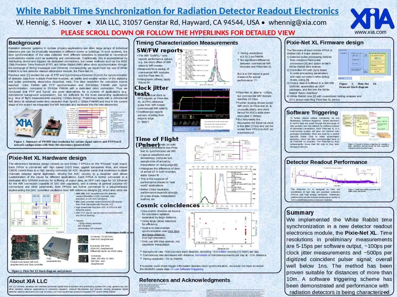
/
Background Radiation detector systems in nuclear physics applications are often large Background Radiation detector systems in nuclear physics applications are often large

Background Radiation detector systems in nuclear physics applications are often large - PowerPoint Presentation

grace3
grace3 . @grace3
Follow
67 views
Uploaded On 2023-11-11

Background Radiation detector systems in nuclear physics applications are often large - PPT Presentation

Previous work 1 studied the use of PTP and Synchronous Ethernet SyncE for synchronization of detector data from multiple PixieNet modules an earlier and smaller version of the digitizing and pulse processing electronics described here The time resolution for coincident events reached 10n ID: 1031099

time xia pixie detector xia time detector pixie net ptp data synchronization rabbit white adc readout clock radiation performance

Share:

Link:

Embed:

Download Presentation from below link

Download Presentation The PPT/PDF document "Background Radiation detector systems in..." is the property of its rightful owner. Permission is granted to download and print the materials on this web site for personal, non-commercial use only, and to display it on your personal computer provided you do not modify the materials and that you retain all copyright notices contained in the materials. By downloading content from our website, you accept the terms of this agreement.


Presentation Transcript

1. BackgroundRadiation detector systems in nuclear physics applications are often large arrays of individual detectors and can be physically separated in different rooms or buildings. In such systems, the time synchronization of the data collected from different detectors is essential to reconstruct multi-detector events such as scattering and coincidences. Traditionally, this is accomplished by distributing clocks and triggers via dedicated connections, but newer methods such as the IEEE 1588 Precision Time Protocol (PTP) and White Rabbit (WR) allow clock synchronization through the exchange of timing messages over Ethernet. Consequently, we report here the use of White Rabbit in a new detector readout electronics module, the Pixie-Net XL.Previous work [1] studied the use of PTP and Synchronous Ethernet (SyncE) for synchronization of detector data from multiple Pixie-Net modules, an earlier and smaller version of the digitizing and pulse processing electronics described here. The time resolution for coincident events reached ~10ns FWHM with PTP synchronization and 200-800ps FWHM with SyncE synchronization, compared to 20-50ps FWHM with a dedicated clock connection. Thus we concluded that PTP and SyncE are good alternatives for a number of applications (e.g. coincidence background suppression), but not sufficient for the most demanding applications (e.g. time of flight measurements requiring <100ps timing). Preliminary tests with a commercial WR demo kit obtained better time resolution than SyncE (~150ps FWHM) and thus in the current stage of the project we integrated the WR firmware and hardware into the new electronics. Pixie-Net XL Hardware designThe electronics hardware design centers on two Kintex 7 FPGAs on the “PXdesk” main board. Each FPGA is connected with high speed LVDS lines, gigabit transceiver lines, and slower CMOS control lines to a high density connector for ADC daughter cards that implement multiple channels detector signal digitization. Moving the ADC circuitry to a daughter card allows customization of the inputs for different applications. Each FPGA is further connected to a dedicated 4Gb SDRAM memory for buffering of output data, an SFP card cage for 1G Ethernet for the WR connection (capable of 10G with upgrades), and a variety of general purpose I/O connections and other peripherals. Both FPGAs are further connected to a daughterboard implementing the DAC controlled oscillators from WR reference designs [2], which also clock the ADCs (with buffers). SummaryWe implemented the White Rabbit time synchronization in a new detector readout electronics module, the Pixie-Net XL. Time resolutions in preliminary measurements are 5-15ps per software output, ~100ps per clock jitter measurements and ~500ps per digitized coincident pulser signal; overall well below 1ns. The method has been proven suitable for distances of more than 10m. A software triggering scheme has been demonstrated and performance with radiation detectors is being characterized 2020 RTCTiming Characterization MeasurementsThe firmware of each Kintex FPGA is divided into 4 major sections: Detector pulse processing derived from previous Pixie pulse processors [4] and option to latch White Rabbit time stamps Controller I/O with Zynq board to write processing parameters and read out data in slow debug mode, using [5]. Output data is buffered in a 256 MB SDRAM, assembled as UDP packages, and fed into the White Rabbit “fabric interface” White Rabbit core [2] with customized Verilog wrapper and GTX pinout matching Pixie-Net XL pinout. Figure 1. Summary of FWHM time resolution for various signal sources and PTP/SyncE network configurations with Pixie-Net electronics (pictured left)[A] Dell PowerConnect 2216 non-PTP[B] back to back, PTP[C] Netgear ProSAFE GS108 non-PTP[D] Toplink TK 1005G, non-PTP[E] Linksys EZXS55W, non-PTP[F] Moxa EDS-405A-PTP, non-PTP (disabled)[G] Moxa EDS-405A-PTP, PTP[H] Oregano syn1588, PTP[I] Artel Quarra 2800, PTPADC DB: ADC daughtercards for detector readout (flexibility in ADC channels, rate, precision, or non-ADC functions)MZ: Zynq controller board (MicroZed [3]) reused from Pixie-Net (optionally PicoZed, PZ)High speed data flow from ADC to FPGA to WR Ethernet outputWR, PTP, SyncE can be used as source for ADC and FPGA clockingTargets: <100ps timing resolution 10G Ethernet processing ~1M pulses/sFully assembled boxPXdesk main board with ADC daughtercards and Zynq controller4-channel, 75-125 MHz,14bit ADC daughtercard 8-channel, 250 MHz,12bit ADC daughtercardDifferential inputs via HDMI cable Figure 2. Pixie-Net XL block diagram and picturesPixie-Net XL Firmware designXIA pulse processing adapted to Kintex boardWR open source unchangedWR open source adaptedFigure 3. Pixie-Net XL firmware block diagramThe WR “SoftPLL” core reports performance values, e.g. the clock offset of WR slave to WR master. Measured for a variety of commercial WR modules and the Pixie-Net XLHistogramm offsets, apply Gauss fit Timing resolutions 4.3-15.3 ps FWHM No significant difference between commercial WR modules and Pixie-Net XLBut is a SW report a good measure for actual performance ??Clock jitter testsProbing actual clock or PPS signals on Pixie-Net XL vs PPS reference pulse from WR master (commercial WR switch)Oscilloscope reports std.dev. of delay from edge to edge (= “jitter”)Pixie-Net XL jitter is ~100ps, but commercial WR module reaches 10-15psFurther probing shows tuned WR clock on Pixie-Net XL is unusually jittery, and clock fanout for ADCs adds even more jitter (~300ps)But fortunately the Recovered RX Ethernet clock is low jitter (17ps) and can be routed from FPGA to ADC as a workaround Blue: WR Master PPS (commercial WR switch)Red: WR Slave PPS (commercial WR-LENYellow: WR Slave PPS (Pixie-Net XL)Time of Flight (Pulser)Two detector signals (or split pulser) connected to two Pixie-Net XL synchronized via WRCapture waveforms and timestamps, compute sub-sample time of arrival by interpolation on rising edge [6]Histogram the difference of time of arrival ΔT in both modules, apply Gauss fit This is the measure of performance closest to “real world” applicationsBelow 100ps resolution, performance depends strongly on pulse shape, interpolation method, etc Cosmic coincidencesUse cosmic showers as source for coincident radiation separated by large distance. Using large (slow) detectors for efficiency.Goal is to demonstrate synchronization over long time and large distance (not high precision)Only use WR time stamps, not waveform interpolation Background rate ~500 counts/s each detector, recording ~8.5 million records (>1 MeV) per day. Coincidence rate decreases with distance. Hundreds of coincidence events per day at ~11m distance. Timing resolution ~70 ns FWHM If modules could share trigger information besides clock synchronization, we would not have to record the 99.984% waste data => use Software Triggering SW/FW reportsSoftware Triggering To further reduce cabling complexity, we are developing “software triggering”, where decisions to record data are made through the exchange of data packets over the network by software instead of hardwired connections. Each Pixie-Net XL in a multi-module system will send out minimal data packages (metadata) which are used by a central Decision Maker (DM) to make accept/reject decisions, which are then communicated back to all Pixie-Net XL modules. The Pixie‑Net XL then independently move their full data to long term storage or discard.Figure 4. Concept of software triggering, for example to apply coincidence decision during the data acquisition without the need of hardwire logic. About XIA LLCXIA LLC invents, develops and markets advanced digital data acquisition and processing systems for x-ray, gamma-ray, and other radiation detector applications in university research, national laboratories and industry. Having pioneered digital detector readout electronics for over 20 years, our most recent new products integrate PTP and/or White Rabbit Prototypes built so farWhite Rabbit Time Synchronization for Radiation Detector Readout ElectronicsW. Hennig, S. Hoover • XIA LLC, 31057 Genstar Rd, Hayward, CA 94544, USA • whennig@xia.comPLEASE SCROLL DOWN OR FOLLOW THE HYPERLINKS FOR DETAILED VIEWwww.xia.comReferences and Acknowledgments[1] W. Hennig, et al, IEEE Trans. Nucl. Sci. 66 (2019), p1182 [2] https://ohwr.org/project/white-rabbit[3] http://zedboard.org/product/microzed[4] https://www.xia.com/dgf_products.html[5] http://xillybus.com/xillybus-lite[6] equivalent to A. Fallu-Labruyere et al, NIM A 579 (2007), p247.[7] M. Lipinski, et al, 2011 IEEE Intl. Symposium on Precision Clock Synchronization for Measurement, Control and CommunicationThis material is based upon work supported by the U.S. Department of Energy, Office of Science, Office of Nuclear Physics under Award Number DE-SC0017223.Disclaimer: "This report was prepared as an account of work sponsored by an agency of the United States Government. Neither the United States Government nor any agency thereof, nor any of their employees, makes any warranty, express or implied, or assumes any legal liability or responsibility for the accuracy, completeness, or usefulness of any information, apparatus, product, or process disclosed, or represents that its use would not infringe privately owned rights. Reference herein to any specific commercial product, process, or service by trade name, trademark, manufacturer, or otherwise does not necessarily constitute or imply its endorsement, recommendation, or favoring by the United States Government or any agency thereof. The views and opinions of authors expressed herein do not necessarily state or reflect those of the United States Government or any agency thereof."Detector Readout Performance The Pixie-Net XL is designed to read out scintillators at high rate and precision detectors (HPGe) with high energy resolution. Preliminary performance results indicate performance similar to XIA’s established pulse processor modules. Figure 5. Multi-source HPGe spectrum with DB02 (12bit, 250 MSPS). 4-channel, 16bit, 250 MHz or 14bit, 500 MHz ADC daughtercard

2. White Rabbit Time Synchronization for Radiation Detector Readout ElectronicsW. Hennig, S. Hoover • XIA LLC, 31057 Genstar Rd, Hayward, CA 94544, USA • whennig@xia.comwww.xia.comMotivation

3. White Rabbit Time Synchronization for Radiation Detector Readout ElectronicsW. Hennig, S. Hoover • XIA LLC, 31057 Genstar Rd, Hayward, CA 94544, USA • whennig@xia.comBackgroundRadiation detector systems in nuclear physics applications are often large arrays of individual detectors and can be physically separated in different rooms or buildings. In such systems, the time synchronization of the data collected from different detectors is essential to reconstruct multi-detector events such as scattering and coincidences. Traditionally, this is accomplished by distributing clocks and triggers via dedicated connections, but newer methods such as the IEEE 1588 Precision Time Protocol (PTP) and White Rabbit (WR) allow clock synchronization through the exchange of timing messages over Ethernet. Consequently, we report here the use of White Rabbit in a new detector readout electronics module, the Pixie-Net XL.Previous work [1] studied the use of PTP and Synchronous Ethernet (SyncE) for synchronization of detector data from multiple Pixie-Net modules, an earlier and smaller version of the digitizing and pulse processing electronics described here. The time resolution for coincident events reached ~10ns FWHM with PTP synchronization and 200-800ps FWHM with SyncE synchronization, compared to 20-50ps FWHM with a dedicated clock connection. Thus we concluded that PTP and SyncE are good alternatives for a number of applications (e.g. coincidence background suppression), but not sufficient for the most demanding applications (e.g. time of flight measurements requiring <100ps timing). Preliminary tests with a commercial WR demo kit obtained better time resolution than SyncE (~150ps FWHM) and thus in the current stage of the project we integrated the WR firmware and hardware into the new electronics. www.xia.comFigure 1. Summary of FWHM time resolution for various signal sources and PTP/SyncE network configurations with Pixie-Net electronics (pictured above)[A] Dell PowerConnect 2216 non-PTP[B] back to back, PTP[C] Netgear ProSAFE GS108 non-PTP[D] Toplink TK 1005G, non-PTP[E] Linksys EZXS55W, non-PTP[F] Moxa EDS-405A-PTP, non-PTP (disabled)[G] Moxa EDS-405A-PTP, PTP[H] Oregano syn1588, PTP[I] Artel Quarra 2800, PTP

4. White Rabbit Time Synchronization for Radiation Detector Readout ElectronicsW. Hennig, S. Hoover • XIA LLC, 31057 Genstar Rd, Hayward, CA 94544, USA • whennig@xia.comwww.xia.comPixie-Net XL Hardware designThe electronics hardware design centers on two Kintex 7 FPGAs. Each FPGA is connected with high speed LVDS lines, gigabit transceiver lines, and slower CMOS control lines to a high density connector for ADC daughter cards that implement multiple channels detector signal digitization. Moving the ADC circuitry to a daughter card allows customization of the inputs for different applications. Each FPGA is further connected to a dedicated 4Gb SDRAM memory for buffering of output data, an SFP card cage for 1G Ethernet for the WR connection (capable of 10G with upgrades), and a variety of general purpose I/O connections and other peripherals. Both FPGAs are further connected to a daughterboard implementing the DAC controlled oscillators from WR reference designs [2], which also clock the ADCs (with buffers). ADC DB: ADC daughtercards for detector readout (flexibility in ADC channels, rate, precision, or non-ADC functions)MZ: Zynq controller board (MicroZed [3]) reused from Pixie-Net (optionally PicoZed, PZ)High speed data flow from ADC to FPGA to WR Ethernet outputWR, PTP, SyncE can be used as source for ADC and FPGA clockingTargets: <100ps timing resolution 10G Ethernet processing ~1M pulses/sFully assembled box4-channel, 75-125 MHz,14bit ADC daughtercard 8-channel, 250 MHz,12bit ADC daughtercardDifferential inputs via HDMI cable Figure 2. Pixie-Net XL block diagram and picturesPrototypes built so farPxdesk main board with ADC daughtercards and Zynq controller4-channel, 16bit, 250 MHz or 14bit, 500 MHz ADC daughtercard White Rabbit Clock Daughterboard

5. White Rabbit Time Synchronization for Radiation Detector Readout ElectronicsW. Hennig, S. Hoover • XIA LLC, 31057 Genstar Rd, Hayward, CA 94544, USA • whennig@xia.comwww.xia.comThe WR “SoftPLL” core reports performance values, e.g. the clock offset of WR slave to WR master. Measured for a variety of commercial WR modules and the Pixie-Net XLHistogramm offsets, apply Gauss fit Timing resolutions 4.3-15.3 ps FWHM No significant difference between commercial WR modules and Pixie-Net XLBut is a SW report a good measure for actual performance ??Clock jitter testsProbing actual clock or PPS signals on Pixie-Net XL vs PPS reference pulse from WR master (commercial WR switch)Oscilloscope reports std.dev. of delay from edge to edge (= “jitter”)Blue: WR Master PPS (commercial WR switch)Red: WR Slave PPS (commercial WR-LENYellow: WR Slave PPS (Pixie-Net XL)SW/FW reports

6. White Rabbit Time Synchronization for Radiation Detector Readout ElectronicsW. Hennig, S. Hoover • XIA LLC, 31057 Genstar Rd, Hayward, CA 94544, USA • whennig@xia.comwww.xia.comTime of Flight (Pulser)Two detector signals (or split pulser) connected to two Pixie-Net XL synchronized via WRCapture waveforms and timestamps, compute sub-sample time of arrival by interpolation on rising edge [6]Histogram the difference of time of arrival ΔT in both modules, apply Gauss fit This is the measure of performance closest to “real world” applicationsBelow 100ps resolution, performance depends strongly on pulse shape, interpolation method, etc

7. White Rabbit Time Synchronization for Radiation Detector Readout ElectronicsW. Hennig, S. Hoover • XIA LLC, 31057 Genstar Rd, Hayward, CA 94544, USA • whennig@xia.comwww.xia.comCosmic coincidencesUse cosmic showers as source for coincident radiation separated by large distance. Using large (slow) detectors for efficiency.Goal is to demonstrate synchronization over long time and large distance (not high precision)Only use WR time stamps, not waveform interpolation Background rate ~500 counts/s each detector, recording ~8.5 million records (>1 MeV) per day. Coincidence rate decreases with distance. Hundreds of coincidence events per day at ~11m distance. Timing resolution ~70 ns FWHM If modules could share trigger information besides clock synchronization, we would not have to record the 99.984% waste data => use Software Triggering

8. White Rabbit Time Synchronization for Radiation Detector Readout ElectronicsW. Hennig, S. Hoover • XIA LLC, 31057 Genstar Rd, Hayward, CA 94544, USA • whennig@xia.comwww.xia.comThe firmware of each Kintex FPGA is divided into 4 major sections: Detector pulse processing derived from previous Pixie pulse processors [4] and option to latch White Rabbit time stamps Controller I/O with Zynq board to write processing parameters and read out data in slow debug mode, using [5]. Output data is buffered in a 256 MB SDRAM, assembled as UDP packages, and fed into the White Rabbit “fabric interface” White Rabbit core [2] with customized Verilog wrapper and GTX pinout matching Pixie-Net XL pinout. Pixie-Net XL Firmware designXIA pulse processing adapted to Kintex boardWR open source unchangedWR open source adaptedFigure 3. Pixie-Net XL firmware block diagram

9. White Rabbit Time Synchronization for Radiation Detector Readout ElectronicsW. Hennig, S. Hoover • XIA LLC, 31057 Genstar Rd, Hayward, CA 94544, USA • whennig@xia.comwww.xia.comTo further reduce cabling complexity, we are developing “software triggering”, where decisions to record data are made through the exchange of data packets over the network by software instead of hardwired connections. Each Pixie-Net XL in a multi-module system sends out minimal data packages (metadata) which are used by a central Decision Maker (DM) to make accept/reject decisions, which are then communicated back to all Pixie-Net XL modules. The Pixie‑Net XL then independently move their full data to long term storage or discard.Figure 4a. Concept of software triggering, for example to apply coincidence decision during the data acquisition without the need of hardwire logic. * = coded decision making, based on WR time stamp, hit pattern, history, …Figure 4b. Data flow in FPGASoftware Triggering

10. White Rabbit Time Synchronization for Radiation Detector Readout ElectronicsW. Hennig, S. Hoover • XIA LLC, 31057 Genstar Rd, Hayward, CA 94544, USA • whennig@xia.comwww.xia.comThe Pixie-Net Xl is designed to read out scintillators at high rate and precision detectors (HPGe) with high energy resolution. Preliminary performance results indicateperformance similar to XIA’s established pulse processor modules. Preliminary tests of the list mode data output throughput, in comparison to previous Pixie DAQ modules are summarized in the plot to the right. Using the “bmon” utility on the receiving PC, we measured RX rates from the Pixie Net-XL of ~122 MB/s or ~200,000 packets/s (above), with each packet containing a list mode record with header and 1us waveform. Data rate, Figure 5. Multi-source HPGe spectrum with DB02 (12bit, 250 MSPS). Detector Readout Performance

11. White Rabbit Time Synchronization for Radiation Detector Readout ElectronicsW. Hennig, S. Hoover • XIA LLC, 31057 Genstar Rd, Hayward, CA 94544, USA • whennig@xia.comwww.xia.comSummaryWe implemented the White Rabbit time synchronization in a new detector readout electronics module, the Pixie-Net XL. Time resolutions in preliminary measurements are 5-15ps per software output, ~100ps per clock jitter measurements and ~500ps per digitized coincident pulser signal; overall well below 1ns. The method has been proven suitable for distances of more than 10m. A software triggering scheme has been demonstrated and performance with radiation detectors is being characterizedKey results:White Rabbit IP core integrated into detector readout pulse processing logicHW design with multiple ADC daughtercard optionsSoftware triggering schemeSub-nanosecond timing resolution in time-of-flight type measurements1Gbps Ethernet data output with White Rabbit synchronization, demonstrated 10Gbps data capability of hardware OutlookTo bring this project to completion, we plan toRevise and finalize the clock circuitry for minimal jitterExplore the Dolosse data management scheme in the data readoutFully characterize timing and detector performance

12. White Rabbit Time Synchronization for Radiation Detector Readout ElectronicsW. Hennig, S. Hoover • XIA LLC, 31057 Genstar Rd, Hayward, CA 94544, USA • whennig@xia.comwww.xia.comAbout XIA LLCXIA LLC invents, develops and markets advanced digital data acquisition and processing systems for x-ray, gamma-ray, and other radiation detector applications in university research, national laboratories and industry. Having pioneered digital detector readout electronics for over 20 years, our most recent new products integrate PTP and/or White RabbitContact:www.xia.comwhennig@xia.com References and Acknowledgments [1] W. Hennig, et al, IEEE Trans. Nucl. Sci. 66 (2019), p1182 [2] https://ohwr.org/project/white-rabbit[3] http://zedboard.org/product/microzed[4] https://www.xia.com/dgf_products.html[5] http://xillybus.com/xillybus-lite[6] equivalent to A. Fallu-Labruyere et al, NIM A 579 (2007), p247.[7] M. Lipinski, et al, 2011 IEEE Intl. Symposium on Precision Clock Synchronization for Measurement, Control and CommunicationThis material is based upon work supported by the U.S. Department of Energy, Office of Science, Office of Nuclear Physics under Award Number DE-SC0017223.Disclaimer: "This report was prepared as an account of work sponsored by an agency of the United States Government. Neither the United States Government nor any agency thereof, nor any of their employees, makes any warranty, express or implied, or assumes any legal liability or responsibility for the accuracy, completeness, or usefulness of any information, apparatus, product, or process disclosed, or represents that its use would not infringe privately owned rights. Reference herein to any specific commercial product, process, or service by trade name, trademark, manufacturer, or otherwise does not necessarily constitute or imply its endorsement, recommendation, or favoring by the United States Government or any agency thereof. The views and opinions of authors expressed herein do not necessarily state or reflect those of the United States Government or any agency thereof."