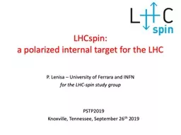
/
LHCspin : a polarized internal target for the LHC LHCspin : a polarized internal target for the LHC

LHCspin : a polarized internal target for the LHC - PowerPoint Presentation

heartersh
heartersh . @heartersh
Follow
343 views
Uploaded On 2020-06-24

LHCspin : a polarized internal target for the LHC - PPT Presentation

PSTP2019 Knoxville Tennessee September 26 th 2019 P Lenisa University of Ferrara and INFN for the LHCspin study group 2 A bit of pre history Tefloncoated storage cell filled with polarized H proposed by Prof W ID: 785578

target beam gas lhc beam target lhc gas cell field polarized proton hera polarization spin large physics luminosity collider

Share:

Link:

Embed:

Download Presentation from below link

Download The PPT/PDF document "LHCspin : a polarized internal target fo..." is the property of its rightful owner. Permission is granted to download and print the materials on this web site for personal, non-commercial use only, and to display it on your personal computer provided you do not modify the materials and that you retain all copyright notices contained in the materials. By downloading content from our website, you accept the terms of this agreement.


Presentation Transcript

Slide1

LHCspin:a polarized internal target for the LHC

PSTP2019Knoxville, Tennessee, September 26th 2019

P. Lenisa – University of Ferrara and INFNfor the LHC-spin study group

Slide2

2

A bit of (pre) historyTeflon-coated storage cell filled with polarized H proposed by Prof. W. Haeberli 2nd Polarization Symposium (Karlsruhe 1965)First test in Madison (Wisconsin): 5th Int. Symp. on Pol. Phenomena in Nuclear Physics (Santa Fe 1980)

Slide3

Motivation

Slide4

4Kinematics for a fixed target at LHC

Slide5

5Advantages of the fixed-target mode (

wrt to collider):Access large-negative xF and large positive xB High luminosities (dense targets)Easy change target typePolarized target – spin physics programPhysics goals:Large-x gluon, antiquark and heavy-quark content in the nucleon and nucleus.Dynamics and spin of gluons in (un)-polarised nucleonsHeavy-ion collisions towards large rapiditiesFixed target mode at LHC: performance

Slide6

SMOG2 development at LHCb

Slide7

LHCb detector

Forward geometry

Conceived for measurements in collider modeIdeal for

fixed

target

experiments

Slide8

SMOG

(System for Measuring Overlap with Gas)Beam-Gas imagingDedicated runs at different energies since 2015

Slide9

9Upgrade to SMOG2

installation of a storage cell in 2019 and start data taking in 2021Opened cellClosed cellLHCbVELO Detector

Slide10

10

Increase luminosity up to 2 orders of magnitude with the same gas loadInjection of H2, D2, 3,4He, N2, Ne, Ar, Kr, XeWell defined interaction region upstream the IP@13TeV:Possible simultaneous data taking with pp interactions @13 TeVSMOG2 vs SMOG

Slide11

11Polarized Gas Target

Slide12

Atomic Beam Source

Target Gas AnalyzerSample Beam PolarimeterTarget B12Polarized atomic beam injected from left

Sample beam:QMS to measure molecular fraction.BRP polarimeter to measure atomic polarization.

The HERMES polarized internal gas target @ HERA (1995-2005)

Slide13

13Performance for transversely polarized H (2002/03)

HERMES 2002/03 data taking with transverse proton polarizationTop: Degree of dissociation measured by the TGA (a = 1: no molecules);Bottom: Vector polarization Pz measured by Breit-Rabi-Polarimeter.Coating: ice layer on Drifilm surface

Slide14

PGT at LHC - topology

Z= 0 LHCb - IPPrototype of the new

system:Transverse magnetAdditional tracking system

Slide15

15Compatibility with LHC beams

Beam half-life: ≈ 10 hParasitic operation requires small reduction of half-life (< 10%)p beam intensities @ LHCProtons: Ip = 6.8∙1018 p/s @ 7 TeV.1s-radius at IP (full energy): < 0.02 mmNegligible compared with the cell radius (> 5 mm)Safety radius at injection (450 GeV

for p): > 25 mm “Openable” cell required.

Beam tube

Length: 300 mm (L

1

= 150 mm)

Closed: D

1

= 10 mm

.

Opened: D

1

= 50 mm

Cell temperature: T = 100 K

.

Slide16

16

Polarized 1H gas target performancespp @ √s = √2MnEp ≈ 100 GeV = 50 mb = 5∙10-26 cm2Max. relative loss rate: (dN/dt)/N = 2∙10-8/s

H, Ctot

= 2 C

1

+ C

2

= 16 l/s, I = 6.5∙10

16

atoms/s (HERMES):

areal density

q

= L

1

r

0

=

1.2∙10

14

atoms/cm

2

Total luminosity:

L

pp

= 8.2∙10

32

/ cm

2

s

About 5% of the collider luminosity

The H target does not affect the life time of the 7

TeV

proton beam

Slide17

(A couple of) accelerator issues

Slide18

Bunch beam structure and Fourier spectrum at LHC

st= 253 pssn= 0.63 GHzDn= 40.08 MHzTemporal structure of the proton

bunchFourier analysis of the proton

beam

Slide19

Beam-induced depolarization (BID)1 - 2

3 - 4

2 - 4

Resonant transitions caused by beam field

Orientation of guide field

B

0

and RF - beam field

B

1

:

p

resonances

for B

1

B

0

D

F = 0, ±1

D

mF

= ± 1

s

resonances

for B

1

||

B

0

D

F = ±1

D

mF

= 0.

Affect nuclear polarization.

s

resonances (

states 2-4

) densely spaced:

high homogeneity of guide field required

p-beam

Slide20

Comparison HERA vs LHC

20Machine

NBunch

f

Bunch

(

MHz)

I

beam

(

A)

s

t

(

ps

)

1/e width of Fourier spectrum

HERA-e

210

10.41

0.04

31

5.1 GHz

LHC

2600

40.08

1.0

253

0.63 GHz

BID

at the LHC negligible

wrt

HERA despite the 25x higher beam current

Spin-flip Probability

s

2-4

resonance

,

q

= mixing angle,

t

= crossing time, n index of passage:

B

||

B

1

-RF

field

parallel

to

B

0

(

guide

field

≈ 300mT)

B

1

|| B

0

for

q

= 90°

.

Relative

strength

of

BID

by

ratio

of

the

square

of

B

||

:

s

2-4

transition

at 8.54 GHz

k-th

harmonic

of

Fourier

spectrum

:

LHC: F

213

= 2 ∙ 1.0 A ∙ 1.53 10

-20

HERA: F

820

= 2 ∙ 0.04 A ∙ 7.53 10

-2

Slide21

Coatings for surfaces close to the LHC beam: materials with SEY ≤ 1.4 allowed

Non-Evaporable Getter (NEG) (standard)Amorphous Carbon (a-C) (tested and applied more frequently)NEG coating for the tube’s inner surface excluded because of its pumping actionH recombination and depolarization on C to be studied Option: C with frozen ice layer to preserve H polarization Secondary Electron Yield (SEY) and cell coating

Slide22

22

SEY of Water: preliminary studiesOnly few layers required;the cell is short (30 cm);laboratory tests to study dynamical equilibrium

ice layer on a-C; test chamber

first in the SPS?

Slide23

Summary

Unique physics opportunities for single-spin physics program at LHCFirst conceptual design developedCell30 cm long-cell (openable at injection)≈ 0.3 T vertical fieldCell surface with a-C coating: To be studiedThin ice layer to suppress recombination and depolarization. Target densities and luminosity depend on the gas load permitted: quite high.Tracker downstream requiredBID estimated: more favorable than at HERMES

Slide24

Which dissociator technology with extreme reliability to be used?

No coolant must flow into the vacuum systemSpace is tight on the side of the beam foreseen for diagnostics. How would a minimal BRP and TGA look like?Is there a p-p channel we could use for polarimetry?see RHIC jet polarimeter detecting recoil p’s from CNI regionNICA is also planning a similar polarimeterHow to enable assembly, service and repair within the limited space?Open issues

Slide25

Spares

Slide26

26Proton-proton collisions: variables

XB: Bjorken-x (0<xB<1)- xB = parton momentum fraction- x1 & x

2 Bjorken-x of beam and target

X

F

:

Feymann

-x (-1<

x

F

<1)

Rapidity (y) and angle with beam axis (

q

)

Collider

Fixed target

y

y

y

y

Slide27

Along the beam:

About 1m, limited by shielding wall. Could be moved, but important for the PGT to stay as close to the VELO as possible!In transverse direction: Enough to place ABS and diagnostics in the horizontal plane (→ Bguide vertcal)Arrangement in the tunnel:available space upstream of the VELO vessel