/
1 1.  Rover5 Powered by Bluetooth 1 1.  Rover5 Powered by Bluetooth

1 1. Rover5 Powered by Bluetooth - PowerPoint Presentation

hondasnoopy
hondasnoopy . @hondasnoopy
Follow
343 views
Uploaded On 2020-08-29

1 1. Rover5 Powered by Bluetooth - PPT Presentation

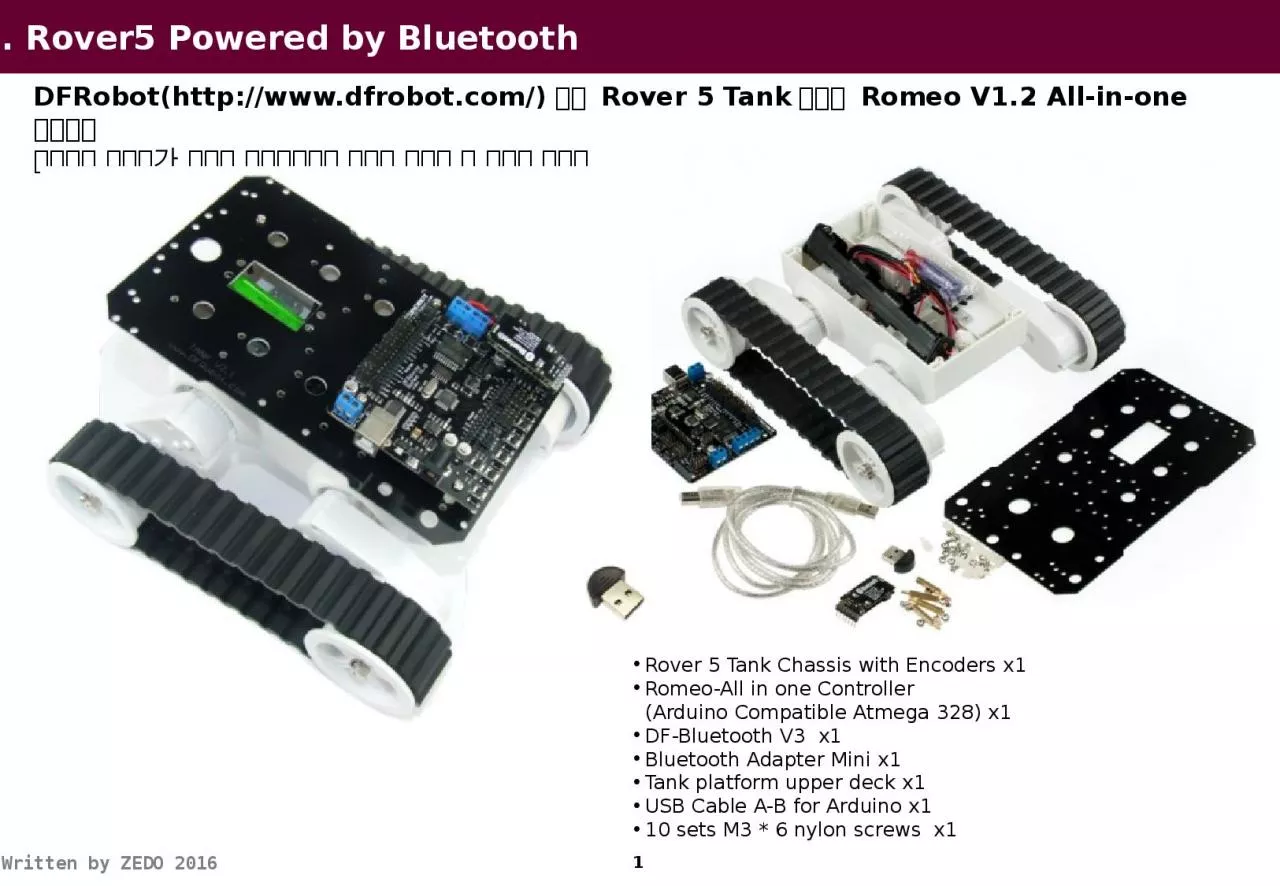
DFRobot httpwwwdfrobotcom 에서 Rover 5 Tank 기반에 Romeo V12 Allinone 컨트롤러 사용하여 사용자가 다양한 컨스터마이징 작업을 수행할 수 있도록 제공함 ID: 810351

results serial println bluetooth serial results bluetooth println key void digitalwrite int char analogwrite 255 turn decode control print

Share:

Link:

Embed:

Download Presentation from below link

Download The PPT/PDF document "1 1. Rover5 Powered by Bluetooth" is the property of its rightful owner. Permission is granted to download and print the materials on this web site for personal, non-commercial use only, and to display it on your personal computer provided you do not modify the materials and that you retain all copyright notices contained in the materials. By downloading content from our website, you accept the terms of this agreement.


Presentation Transcript

Slide1

1

1.

Rover5 Powered by Bluetooth

DFRobot(http://www.dfrobot.com/)에서 Rover 5 Tank기반에 Romeo V1.2 All-in-one 컨트롤러 사용하여 사용자가 다양한 컨스터마이징 작업을 수행할 수 있도록 제공함

Rover 5 Tank Chassis with Encoders x1

Romeo-All in one Controller

(

Arduino

Compatible

Atmega

328) x1

DF-Bluetooth V3  x1

Bluetooth Adapter Mini x1

Tank platform upper deck x1

USB Cable A-B for

Arduino

 x1

10 sets M3 * 6 nylon screws  x1

Slide2

2

2.

Rover5 -

연결도LEFTRIGHTDIO

4~7는

모터 제어를 위해 사용함

A7

+

-

+

-

Slide3

3

3.

Rover5

- 구성궤도를 조정 가능함Encoder

를 통하여

모터의 속도 조절 가능함

Slide4

4

4.

Bluetooth (1/6) : DF-Bluetooth

DF-Bluetooth는 모바일폰이나 노트북에서 제어가 가능하도록 TTL level UART 인터페이스를 제공한다.Chips: CSR BC417143 Bluetooth Protocol: Bluetooth Specification v2.0 +EDR Working Frequency: 2.4-2.48GHz unlicensed ISM Band Modulation Mode: GFSK (Gaussian Frequency Shift Keying)

Power: ≤4dBm, Class 2

Transmission Distance: 20-30 in free space

Sensitivity: ≤-84

dBm

at 0.1% BER

Transmission rate: Asynchronous: 2.1 Mbps (Max)/160 kbps; Synchronous: 1Mbps/1Mbps

Security: Authentication and encryption

Support profiles: Bluetooth serial port

LED indicator: LINK

Power Supply: +3.5V-+8V DC/50

mA

Working Temperature: -20°C-+55°C

Dimension: 43x19.3x11mm

Bluetooth

V3

모듈은

2

개의 스위치가 있다

.

NO.1

스위치는

LINK-LED

on/off

용도

(

기본

: On)

이며

NO.2

스위치는 AT mode 설정으로 Bluetooth 모듈 제어한다. AT mode (On)Functional mode(Off)NO.2 스위치를 On할 경우 AT 모드로 Bluetooth 모듈을 설정할 수 있다.

LINK-LED

on/off(Default : On)AT Mode on/off(Default : Off)

주의 사항

:

DF-Bluetooth

Arduino

상에서 사용할 때

,

Arduino

로 프로그램을

Upload

할때

DF-Bluetooth

모듈을 제거해야 한다

.

사유는

DF-Bluetooth

모듈에서

TX/RX pin

을 점유해서 사용하기 때문임

Slide5

4.

Bluetooth (2/6) : Bluetooth Adaptor

Bluetooth Adaptor Mini는 PC

나 노트북에서 Bluetooth 연결이 가능하게 한다.Bluetooth standard 2.0 * USB Interface: USB2.0 standardIn the 2.4GHz to 2.483GHz frequency band operation between the use FHSS (Frequency Hopping Spread Spectrum) technologyOpen space under the operational range of about 10 metersIntuitive software user interface, without complicated settingsFor Windows 98SE/ME/2000/XP or Mac OS X 10.2.6 or higher operating system

Sensitivity <-85 dBM

Data transfer rate up to 3M bps Features

PC

에 아답터를 연결하면

Windows Update

에서 해당 드라이브를 설정함

Bluetooth Adaptor

설치 완료

Slide6

4.

Bluetooth (3/6) : Connection

PC에서 Rover5 Bluetooth 모듈과 연결시 기본 비밀번호는

“1234”로 입력함PC의 Task Bar

에서 Bluetooth

아이콘을

Click

Rover5

Bluetooth

장치를 추가함

(Bluetooth_V3)

2

1

3

Paring Code

입력을 선택함

4

Paring Code “1234”

입력함

5

장치관리자에서

COM8, COM9

포트 설정된 것을 확인 가능함

Slide7

4.

Bluetooth (4/6) : AT Mode

Rover5 Bluetooth 모듈을 AT 모드에서 설정값을 변경하기 위하여

CoolTerm을 사용함Part 1: Ready to goRover5의 Romeo에 Bluetooth 모듈을 삽입한다.Bluetooth

모듈의 AT 모드 스위치를

On

한다

.

PC

Bluetooth

아답터를

USB

에 연결한다

.

PC에서 Bluetooth

아답터를 인식(USB to Serial)하고 Rover5

의 Bluetooth 모듈과 연결한다.(

연결시 비밀번호

“1234”)

Part 2:

Setting

PC

Bluetooth

모듈이 연결된 후

CoolTerm

을 사용하여

Bluetooth

모듈과 통신한다

.

CoolTerm

”을 실행 시킨 후에1. Connection --> Options에서 아래 파라미터를 조정한다.2. Set Serial Port - 장치관리자에서 Bluetooth로 지정된 Serial Port를 지정한다. - Baudrate: 9600 - Data Bits: 8

- Parity : none - Stop

Bits: 1 3. Set Terminal - Terminal Mode: Line Mode - Key

Emulation: CR+LF

장치관리자에서

Usb

to Serial Port

설정한다

.

COM8.

COM8.

Slide8

4.

Bluetooth (5/6) : AT Mode

Rover5 Bluetooth 모듈과 연결하기 위하여

CoolTerm(http://freeware.the-meiers.org/)를 사용함Part 3: SettingCoolTerm을 사용하여 AT 명령을 Bluetooth 모듈로 전송하여 어떻게 응답하는지 확인하자. Bluetooth 모듈의

AT 모드 스위치를

On

한다

.

1.

입력

: at

응답

:

OK

2. 입력 :

at+name=DFRobot

응답 :

OK

3.

입력

:

at+name

?

응답

:

+

name:

DFRobot

OK

4.

입력 : at+role=0 응답 : OK 5. 입력 : at+role? 응답 : +role:0 OK 6. AT+PSWD?

+PSWD:1234 OK

7. AT+ORGL (Restore the default setting:)

응답

:

OK

8. AT+UART=115200,0,0

응답

:

OK

Param1

: baud rate (bits/s) 4800/ 9600/ 19200/

38400

/ 57600/ 115200/ 230400/ 460800

/

912600/ 1382400

Param2

: stop bit , 0- 1 bit/ 1- 2 bits

Param3

: parity bit, 0- None/ 1- Odd/ 2- Even

9. AT+RESET

응답

:

OK

[

기본 설정

]

Device

class: 0

Inquiry code: 0x009e8b33

Device mode: Slave mode

Binding mode: SPP

Serial port: 38400 bits/s; 1 stop bit, no parity (In datasheet, it said the default baud rate is 9600 which is wrong.)

Pairing code: “1234”

Device name:

Bluetooth V3

Slide9

4.

Bluetooth (6/6) : SPP Mode

Rover5 Bluetooth

모듈의 AT Mode을 Off로 하고 휴대폰과 통신하도록 하자.http://www.dfrobot.com/forum/viewtopic.php?f=5&t=1659 참조DF-Bluetooth을 Arduino

상에서 사용할 때

,

Arduino

로 프로그램을

Upload

할때

DF-Bluetooth

모듈을 제거해야 한다

.

사유는

DF-Bluetooth

모듈에서

TX/RX pin

을 점유해서 사용하기 때문임

통신 속도는 9600bps

로 설정하고

PC(

CoolTerm

)

혹은 휴대폰에서 제어 가능하다

.

String

val

= "";

boolean

mark = LOW;

void setup() {


Serial.begin

(

9600);  //initial the Serial  pinMode(13, OUTPUT);}void loop() {  while (Serial.available()) {    val += char(Serial.read());    delay(2);   // Can't be deleted for it needs time to read serial    mark = HIGH;  }  if (val.length() == 1) {    //Send command without CR/ LF/ NL    if (val == "1") {      Serial.println("LED is ON!");    }    else if (val == "0") {      Serial.println("LED is OFF!");    }  }  if (mark == HIGH) {    Serial.print("Length: ");      Serial.println(val.length());    Serial.print("Val: ");        Serial.println(val

); delay(50);    Serial.println("Done");       Serial.println();   

Serial.flush();    val = "";    mark = LOW;  }}

Slide10

10

5. Code-

Remeo V1.2

Button Control(1/2)char msgs[5][15] = { "Right Key OK ", "Up Key OK ", "Down Key OK ", "Left Key OK ", "Select Key OK" };char start_msg[15] = { "Start loop "}; int

adc_key_val[5] ={ 30, 150, 360, 535, 760 };

int

NUM_KEYS = 5;

int

adc_key_in

;

int

key=-1;

int

oldkey

=-1;void setup() { //

pinMode(13, OUTPUT); //we'll use the debug LED to output a heartbeat Serial.begin(9600);

/* Print that we made it here */ Serial.println

(start_msg); }

DFRduino

RoMeo

5

개의 버튼

(S1-S5)

이 있으며 하나의

Analog

입력

(A7)

을 사용함

5

개의

Key

를 사용하기

Slide11

11

5. Code-

Remeo V1.2 Button Control(2/2)

void loop() { adc_key_in = analogRead(A7); // read the value from the sensor // digitalWrite(13, HIGH); /* get the key */ key = get_key(adc_key_in); // convert into key press if (key !=

oldkey) { // if keypress

is detected

delay(50); // wait for

debounce

time

adc_key_in

=

analogRead

(0); // read the value from the sensor

key = get_key

(adc_key_in); // convert into key press

if (key != oldkey) { oldkey

= key; if (key >=0){ Serial.println

(adc_key_in, DEC); Serial.println(

msgs

[key]);

}

}

}

//

digitalWrite

(13, LOW);

}

// Convert ADC value to key number

int

get_key

(unsigned

int

input){ int k; for (k = 0; k < NUM_KEYS; k++) { if (input < adc_key_val[k]) { return k; } } if (k >= NUM_KEYS) k = -1; // No valid key pressed return k;}DFRduino RoMeo는 5개의 버튼(S1-S5)이 있으며 하나의 Analog 입력

(A7)을 사용함

Slide12

12

5. Code-

Remeo V1.2 Moter

Control(1/2)//Standard PWM DC control// Romeo V1.2(Arduino UNO)int S1 = 5; //Speed Control(왼쪽)int S2 = 6; //Speed Control(오른쪽)int D1 = 4; //Direction Control(왼쪽)int D2 = 7; //Direction Control(오른쪽)void stop(void) //Stop{ analogWrite(S1,0); digitalWrite(D1,LOW);

analogWrite(S2,0); digitalWrite(D2,LOW);

}

void advance(char

a,char

b) //Move forward

{

analogWrite

(S1,a); //PWM Speed Control

digitalWrite(D1,HIGH);

analogWrite (S2,b); digitalWrite(D2,HIGH);}

Romeo

V1.2의 PWM

직렬 모터 제어는 2개의 디지털 IO

핀(4, 7)과

2

개의

PWM

(5, 6)

으로 구성됨

1

번 모터

(

오른쪽

)

2

번 모터

(

왼쪽

)

Slide13

13

5. Code-

Remeo V1.2 Moter

Control(2/2)void back_off (char a,char b) //Move backward{ analogWrite (S1,a); digitalWrite(D1,LOW); analogWrite (S2,b); digitalWrite(D2,LOW);}void turn_L (char a,char b) //Turn Left(왼쪽으로 빙빙 돌기){ analogWrite (S1,a); digitalWrite

(D1,LOW); // 왼쪽 모터가 뒤로 돌기 analogWrite

(S2,b);

digitalWrite

(D2,HIGH); //

오른쪽 모터가 앞으로 돌기

}

void

turn_R

(char a,char b) //Turn Right(오른쪽으로 빙빙 돌기

){ analogWrite (S1,a); digitalWrite(D1,HIGH); // 왼쪽 모터가 앞으로로 돌기

analogWrite (S2,b); digitalWrite

(D2,LOW); // 오른쪽 모터가 뒤로 돌기}void setup(void) { int i

; for(i=4;i<=7;i++) pinMode(i, OUTPUT);

Serial.begin(9600); //Set Baud Rate Serial.println("Run keyboard control"); // 키보드로 제어하기 analogWrite(S1,LOW);

analogWrite

(S2,LOW);

}

Romeo V1.2

PWM

직렬 모터 제어는

2

개의 디지털

IO

(4, 7)

2

개의 PWM 핀(5, 6)으로 구성됨void loop(void) { if(Serial.available()){ char val = Serial.read(); if(val != -1) { switch(val) { case 'w'://Move Forward Serial.println("Move Forward"); advance (255,255); //move forward in max speed break; case 's'://Move Backward Serial.println("Move Backward"); back_off (255,255); //move back in max speed break; case 'a'://Turn Left Serial.println("Turn Left"); turn_L (255,255); break;

case 'd'://Turn Right Serial.println("Turn Right"); turn_R (255,255);

break; case 'z': Serial.println("Hello"); break; case 'x': Serial.println("Stop"); stop(); break; } }

else stop();

}

}

Slide14

14

5. Code-

적외선 원격 제어(키값 읽기

)포토 트랜지스터를 Romeo V1.2에 설치하여 리모콘에서 전달되는 값을 읽어 보자포토 트랜지스터를

Romeo V1.2

아나로그

단자

(

A0)

에 연결한다

.

-

A7

은 보드의 버턴에 사용

// Photo Transistor example

#include <

IRremote.h

>//IR

라이브러리 포함

int

RECV_PIN = A0;//

포트선언

IRrecv

irrecv

(RECV_PIN);

decode_results

results;//

구조선언

void setup() {

Serial.begin

(9600);

irrecv.enableIRIn();}void loop() { if(irrecv.decode(&results)){ Serial.println(results.value, HEX); irrecv.resume(); // Receive the next value }}

Slide15

15

5. Code-

적외선 원격 제어(리모콘의 제조사 확인

)포토 트랜지스터에 신호를 전달하는 리모콘의 제조사와 키값을 확인하자.#include <IRremote.h>//IR 라이브러리 포함int RECV_PIN = A0;//포토 트랜지스터 포트 설정long on1 = 0x00FF6897;//수신된 신호long off1 = 0x00ff30CF;long on2 = 0x00FF9867;long off2 = 0x00FF18E7;long on3 = 0x00FFB04F;long off3 = 0x00FF7A85;long on4 = 0x00FF10EF;

long off4 = 0x00FF42BD;long on5 = 0x00FF38C7;long off5 = 0x00FF4AB5;long on6 = 0x00FF5AA5;

long off6 = 0x00FF52AD;

IRrecv

irrecv

(RECV_PIN);

decode_results

results;//

구조 선언

void dump(decode_results *results){

int count = results->rawlen; if (results->decode_type == UNKNOWN) {

Serial.println("Could not decode message"); } else

{ if (results->decode_type == NEC) { Serial.print("Decoded NEC: "); }

else if (results->decode_type == SONY) { Serial.print("Decoded SONY: "); } else if (results->

decode_type == RC5) { Serial.print("Decoded RC5: "); } else if (results->

decode_type

== RC6)

{

Serial.print

("Decoded RC6: ");

}

Serial.print

(results->value, HEX);

Serial.print

(" (");

Serial.print

(results->bits, DEC); Serial.println(" bits)"); } Serial.print("Raw ("); Serial.print(count, DEC); Serial.print("): "); for (int i = 0; i < count; i++) { if ((i % 2) == 1) { Serial.print(results->rawbuf[i]*USECPERTICK, DEC); } else { Serial.print(-(int)results->rawbuf[i]*USECPERTICK, DEC); } Serial.print(" "); } Serial.println("");}void setup(){ pinMode(RECV_PIN, INPUT); //포트모드,입력 Serial.begin(9600); //전송속도 9600bps irrecv.enableIRIn(); // Start the receiver}int on = 0;unsigned long last =

millis();

void loop() { if (irrecv.decode(&results)) //디코딩 { // If it's been at least 1/4 second since the last // IR received, toggle the relay if (

millis

() - last > 250)

{

on = !on;

digitalWrite

(13, on ? HIGH : LOW);

dump(&results);

}

if (

results.value

== on1 )

Serial.println

("on1");

if (

results.value

== off1 )

Serial.println

("off1");

if (

results.value

== on2 )

Serial.println

("on2");

if (

results.value

== off2 )

Serial.println

("off2");;

if (

results.value

== on3 )

Serial.println("on3"); if (results.value == off3 ) Serial.println

("off3"); if (results.value == on4 ) Serial.println("on4");

if (

results.value

== off4 )

Serial.println("off4");; if (results.value == on5 ) Serial.println("on5"); if (results.value == off5 ) Serial.println("off5"); if (results.value == on6 ) Serial.println("on6"); if (results.value == off6 ) Serial.println("off6"); last = millis(); irrecv.resume(); // Receive the next value }}

Slide16

16

5. Code-

적외선 원격 제어(Rover5 제어

)적외선 원격 제어를 통해 MiniQ를 구동해 보자#include <IRremote.h>//IR 라이브러리 포함int RECV_PIN = A0;//포토 트랜지스터 포트 설정long go = 0x00FF18E7;//버튼2long back = 0x00FF4AB5;//버튼8long left = 0x00FF10EF;//버튼

4long right = 0x00FF5AA5;//버튼6long stop = 0x00FF38C7;//

버튼

5

IRrecv

irrecv

(RECV_PIN);

decode_results

results;//

구조 선언unsigned long last =

millis();int S1 = 5; // Speed Control(왼쪽)int S2 = 6; // Speed Control(오른쪽

)int D1 = 4; // Direction Control(왼쪽)

int D2 = 7; // Direction Control(오른쪽) void brake(void) //Stop{

digitalWrite(S1,0); digitalWrite(D1,LOW); digitalWrite(S2,0);

digitalWrite(D2,LOW); } void advance(char a, char b) //Move forward{ analogWrite (S1,a); //PWM Speed Control

digitalWrite

(D1,HIGH);

analogWrite

(S2,b);

digitalWrite

(D2,HIGH);

}

void

back_off

(char a, char b) //Move backward

{

analogWrite (S1,a); digitalWrite(D1,LOW); analogWrite (S2,b); digitalWrite(D2,LOW);}void turn_L (char a, char b) //Turn Left(왼쪽으로 빙빙 돌기){ analogWrite (S1,a); digitalWrite(D1,LOW); // 왼쪽 모터가 뒤로 돌기 analogWrite (S2,b); digitalWrite(D2,HIGH); // 오른쪽 모터가 앞으로 돌기}void turn_R (char a, char b) //Turn Right(오른쪽으로 빙빙 돌기){ analogWrite (S1,a); digitalWrite(D1,HIGH); // 왼쪽 모터가 앞으로로 돌기 analogWrite (S2,b); digitalWrite(D2,LOW); // 오른쪽 모터가 뒤로 돌기} void setup(){ for(int i=4;i<=7;i++) pinMode(i, OUTPUT); digitalWrite(S1,LOW); digitalWrite(S2,LOW); pinMode(RECV_PIN, INPUT); //

포트모드,입력 irrecv.enableIRIn(); // Start the receiver Serial.begin(9600); //Set Baud Rate

//advance(255,255);}void dump(decode_results *results){ if (results->decode_type == UNKNOWN) { //Serial.println("Could not decode message"); brake();

}

}

void loop()

{

if (

irrecv.decode

(&results)) //

디코딩

{

//

If it's been at least 1/4 second since the last

// IR received, toggle the relay

if (

millis

() - last > 250) //1/4

초 이후 신호 수신의 경우

{

dump(&results);//

적외선 신호 디코딩

}

if (

results.value

== go )

advance(255,255);

else if (

results.value

== back )

back_off

(255,255);

else if (

results.value

== left ) turn_L(255,255);

else if (

results.value

== right )

turn_R(255,255); else if (results.value == stop ) brake(); last = millis(); irrecv.resume(); // Receive the next value }}

Slide17

17

유첨

. Romeo V1.2 -

Arduino with Motor Driver로미오 보드는 아두이노 우노와 같은 ATmega328 칩을 사용하며 2개의 DC 모터 드라이버와 블루투스 소켓이 내장되어 다양한 프로젝트에서 구현 가능함

Slide18

18

유첨

. Rover5 Quadrature

Encoders(1/2)

Slide19

19

유첨

. Rover5 Quadrature

Encoders(2/2)