/
Bypass Diode Effects in Shaded Conditions Bypass Diode Effects in Shaded Conditions

Bypass Diode Effects in Shaded Conditions - PDF document

jane-oiler
jane-oiler . @jane-oiler
Follow
407 views
Uploaded On 2016-02-25

Bypass Diode Effects in Shaded Conditions - PPT Presentation

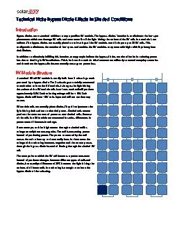
Technical Note x2013 x2013 82010 Introduction Bypass diodes are a standard addition to any crystalline PV module The bypass diodesx2019 function is to eliminate the hot spot phenomena ID: 230464

Technical Note – – 8/2010 Introduction Bypass diodes are

Share:

Link:

Embed:

Download Presentation from below link

Download Pdf The PPT/PDF document "Bypass Diode Effects in Shaded Condition..." is the property of its rightful owner. Permission is granted to download and print the materials on this web site for personal, non-commercial use only, and to display it on your personal computer provided you do not modify the materials and that you retain all copyright notices contained in the materials. By downloading content from our website, you accept the terms of this agreement.


Presentation Transcript

Technical Note Bypass Diode Effects in Shaded Conditions Introduction Bypass diodes are a standard addition to any crystalline PV module. The bypass diodes’ function is to eliminate the hot - spot phenomena which can damage PV cells and even cause fire if the light hitting the surface of the PV cells in a module is not uniform. The bypass diodes are usually placed on sub - strings of the PV module, one dio de per up to 20 PV cells. This configuration eliminates the creation of hot - spots and enables the PV modules to operate with high reliability throughout their lifetime. In addition to effectively fulfilling this function, many people believe the bypass dio des are also effective in reducing power loss due to shading in PV installations. This is far from the truth. In this document we will analyze several everyday scenar ios and show how the bypass diodes can actually cause great power loss. PV Module S tructure A standard 60 cell PV module is usually built from 3 substrings, each protected by a bypass diode. The 3 substrings are serially connected to each other to form the PV module. As long as the light hitting the surface of the PV module cells is uniform, each cell will produce approximately 0.5V. Each substring voltage will be +10V. Each bypass diode will have - 10V at its input and will not conduct any current. PV module cells are actually photodiodes. They directly convert the light hitting their surface to electrical power. Shaded cells cannot produce the same amount of power as non - shaded cells. Because all the cells in a PV module are connected in series, differences in power cause differences in voltage. If one attempts to drive high current through a shaded cell its voltage actually becomes negative. The cell is consuming p ower instead of producing power. The power consumed by the cell causes the cell to heat up and eventually burn. In these cases the voltage of the substring becomes negative and the current passes through the bypass diode instead of flowing through the shad ed PV cell. The exact point at which the PV cell becomes a power consumer instead of producer changes between different types of cells and diodes, but usually a difference of 20% between the light hitting the surfaces of different cells in a substring is e nough to activate the bypass diode of the substring. 2 Traditional ( Centralized ) PV Inverter S ystem A standard PV system comprises strings of PV modules connected in series to an inverter. The inverter’s task is to extract th e maximum power which can be produced from the modules by controlling their current or voltage, and to convert the produced power from DC voltage to grid synchronized AC voltage. For our example we take a system which comprises a single string of 10 modules connected to an inverter. In this example we assume PV module #3 has a single cell which receives 20% less light than its neighbors. Since the current flowing through the entire string is identical for all modules (serial connection), the centralized inverter has 2 options: 1. To work at the maximum power point of all of the modules while activating the b ypass diode of the partially shaded substring in module #3. In this case the power produced from the string would be 9*10% + 1*6.6% = 96.6% of full power. 2. To reduce the current to 80%, ensuring the bypass diode in module #3 will not be activated. In this c ase the power produced would be 10*8% = 80% of full power. In a SolarEdge installation, with a power optimizer MPP tracker on each module, 9*10% + 1*8% = 98% of full power would be produced (all modules have maximum current flowing through them except for module #3 which has 80% of the current flowing through it). In this example we see that a very small obstruction, which reduces the amount of light reaching a single PV cell in one module, can cause a loss of 3.4% of total power production due to the cent ralized MPPT and bypass diodes. This loss can be recovered using the SolarEdge system which includes module level MPP trackers. 1 2 3 9 10 = ~ 3 Another common case is shade which affects the bottom part of a PV module. We will consider the same PV system as described above. We will assume that the shaded region of the bottom cells is 30% of the cell area. In this case the MPPT in the centralized inverter has the following options : 1. To drive full current through the modules, losing all power from the shaded module: 9*10% + 1*0% = 90% of full power. 2. To drive 70% of the current so all modules produce power. In this case 10*7% = 70%. It is clear again that the better option is the first one which produces 90% of the maximum possible power. A SolarEdge system, with module - level MPP trackers, would in this case e nable the production of 9*10% + 1*7% = 97% of full power. This is a 7% increase in power production compared to the optimal case in a traditional system. Multiple S tring I nstallations In multiple string installations the shading effects can be much larger. The electrical constraint of having all strings which are connected in parallel operating at the same voltage does not enable a shaded string to activate its bypass diodes. In many cases shade on PV modules in one of the strings can actually reduce the po wer produced by the entire string. We will take one un - shaded string and one string that is shaded in the manner described in the previous example. The MPPT will enable the production of full power from the first string, and the production of 70% of full power from the second string. In this way both strings reach the same voltage. The power produced in this case would be 85% of maximum possible power. The SolarEdge system could produce 100% of power from the first string and 97% of power from the second string. This would achieve 98.5% of possible power. This is a 13.5% increase in power production compared the traditional case. + -