PDF-Connection Design for Steel Structures
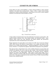
Gusset plates are used in steel buildings to connect bracing members to other structural members in the lateral force resisting system Figure 1 shows a typical vertical
Download Presentation
"Connection Design for Steel Structures" is the property of its rightful owner. Permission is granted to download and print materials on this website for personal, non-commercial use only, provided you retain all copyright notices. By downloading content from our website, you accept the terms of this agreement.
Presentation Transcript
Transcript not available.