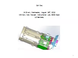
J Bessuille June 2013 Oct 2013 Model File Name CompositeBeamTest File Configuration Default Model Type Solid Loads 1000 Nm uniform Restraints Fixed ends Contacts Bonded Filler Generic GFRP E49 ID: 466998
Download Presentation The PPT/PDF document "FEA of Coil Supports" is the property of its rightful owner. Permission is granted to download and print the materials on this web site for personal, non-commercial use only, and to display it on your personal computer provided you do not modify the materials and that you retain all copyright notices contained in the materials. By downloading content from our website, you accept the terms of this agreement.
Slide1
FEA of Coil Supports
J
Bessuille
June 2013
– Oct 2013 Slide2
Model
File Name
CompositeBeamTestFile ConfigurationDefaultModel TypeSolidLoads1000 N/m, uniformRestraintsFixed endsContactsBonded
Filler: “Generic GFRP”; E=49
GPa
E
eff
= 89.5
GPa
1. Create a composite beam that represents the geometry of the coils (copper + GFRP)
2. Simulate that beam to determine the deflection under simple boundary conditions
3. Use linear elastic model to determine effective stiffness,
E
effSlide3
Model
File Name
Coil+Carrier Assy.SLDASMFile ConfigurationFEA
Model TypeSolid, StaticLoadsGravity + Toroid Force (3000 lb)RestraintsSpine Fixed
ContactsBonded
12.9
deg
from
vertical – 0.359 mm
Horizontal: 0.354 mm
No Contact between coil and clamp plate
No Contact between coil and
strongback
Load Path:
Coil
Blocks
Plates
StrongbackSlide4
More realistic supports – Clamped Ends
Added 8” extra depth to spine of
stongback to counterbalance new boundary conditionThis brings the overall diameter of the 7 coil+carrier assemblies to ~60”This is a workable concept that will be further detailed and analyzed.Horizontal: 3.73 mm
12.9
deg
from vertical: 1.14 mm
ModelFile Name
Coil+Carrier Assy.SLDASMFile
ConfigurationFEA (revised)
Model TypeSolid, StaticLoadsGravity + Toroid
Force (3000 lb)Restraints
Ends FixedContactsBondedSlide5
Model
File Name
Moller_Coil Strongback.sldprtFile ConfigurationFEA, and FEA (6Strut)Model TypeSolid, StaticLoadsGravity + Coil Weight (265 kg) + Toroid Force (3000 lb)Restraints
Ends Fixed, and 3 pin kinematicContactsnone
Clamped Vertical
Clamped Horizontal
Displacement mag. [mm]1.1393.997
6-Strut
Vertical
6-Strut
Horizontal
Displacement
mag. [mm]
2.942
3.625
X + Y
X + Y
Phi + Z
Compare clamped ends to kinematic 6-strut support
Note: Both end pins co-axial. All 3 pin axes intersect predicted CG of
coil+carrier
assemblySlide6
Model
File Name
Moller Hybrid Support Stand Weldment ASSY.SLDASM (Rev A)Slide7
Model
File Name
Moller Hybrid Support Stand Weldment ASSY.SLDASM (Rev A)File ConfigurationFEA2Study Name
Hanging, Floor, and BaselineModel TypeSolid, Static, mixed solid/beamLoads (common)Gravity + Toroid
Force (3000 lb)Restraints
variousContactsbonded solid-solid , bonded beam-solid
7 carrier end faces fixed
End spider fixed, rigid
BASELINE
Hanging
On Floor
Fixed 2 top end surfaces
Fixed 6 top beam nodes
Fixed 2 bottom end surfaces
First pass at analyzing Frame
Beam Elements
Solid ElementsSlide8
Model
File Name
Moller Hybrid Support Stand Weldment ASSY.SLDASM (Rev A)File ConfigurationFEA2
Study NameCraneModel TypeSolid, Static, mixed solid/beamLoads (common)Gravity + Toroid Force (3000
lb)Restraints
4 NodesContactsbonded solid-solid , bonded beam-solidCrane
Fixed 4 top beam nodes
Quick check of stresses in beams: Worst case while lifting with craneSlide9
Condition
Deflection [mm]
Baseline3.125Hanging7.513Floor7.523
Crane8.858
Baseline deflection
Hanging deflection
Why are the floor and hanging deflections so similar? The main difference between the models is that with the hanging condition, the upper z-beams are supported along their length, while for the floor condition, only the frame ends are supported. Looking at the reaction forces for the hanging case, we see that the vertical load carried by the z-beams is more than an order of magnitude less that that supported by the ends.
Beam
rxn
= (2.88+2.47)e3 N = 545
kgf
End
rxn
= (3.51+3.44)e4 N = 7085
kgf
Hanging reactionsSlide10
Right: The highest stress was seen at the DS end of the hanging condition. At 92.6
MPa
, it is well below the yield strength of 6061-T6 (275 MPa) but is still an area of concern. Because the mesh size here is relatively coarse (compared to salient dimensions of the parts), further studies should refine the mesh in these areas. Left: A look at the strain at the DS end shows a great deal of twisting on the fingers and heptagon supports. Since these members transfer the coil end support conditions (i.e. slope) to the frame, reducing strain here will improve overall deflection. Increasing torsional stiffness should reduce twisting
Hanging
The beam stresses are very low (-3.0 – 2.3
MPa
) in the hanging and floor-supported models. This is because the ends of the frame, where the coil load is borne, are directly supported by either the
vacuuim
chamber (hanging) or the ground (floor). It is likely some of these members can be made smaller / thinner.