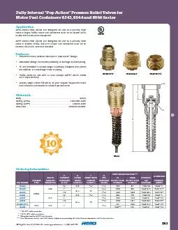
/
insertion-type pressure or temperature probes.All valves are rated fro insertion-type pressure or temperature probes.All valves are rated fro

insertion-type pressure or temperature probes.All valves are rated fro - PDF document

karlyn-bohler
karlyn-bohler . @karlyn-bohler
Follow
429 views
Uploaded On 2016-05-12

insertion-type pressure or temperature probes.All valves are rated fro - PPT Presentation

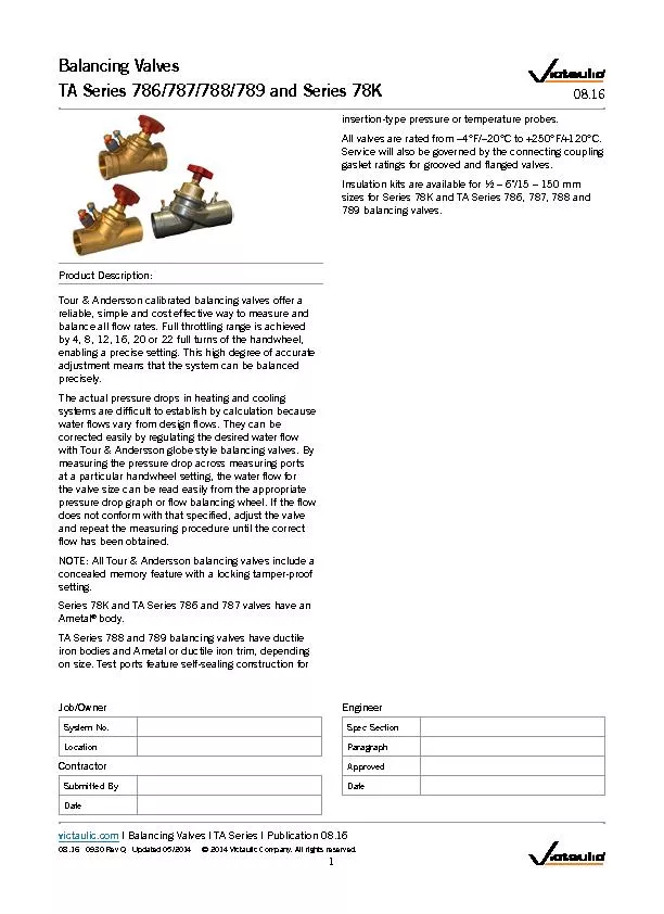
Product DescriptionTour Andersson calibrated balancing valves offer a 1 victauliccom Balancing ValvesTA Series 786787788789 and Series 78K 0816 JobOwnerSystem NoLocationContractorSubmitted ID: 316990

Product Description:Tour Andersson calibrated

Share:

Link:

Embed:

Download Presentation from below link

Download Pdf The PPT/PDF document "insertion-type pressure or temperature p..." is the property of its rightful owner. Permission is granted to download and print the materials on this web site for personal, non-commercial use only, and to display it on your personal computer provided you do not modify the materials and that you retain all copyright notices contained in the materials. By downloading content from our website, you accept the terms of this agreement.


Presentation Transcript

victaulic.com08.16 0930 Rev T Updated 02/2020 © 2020 Victaulic Company. All rights reserved. 1.0PRODUCT DESCRIPTIONAvailable Sizes½ – 16"/DN15 – DN400 Maximum Working Pressure 1 ALWAYS REFER TO ANY NOTIFICATIONS AT THE END OF THIS DOCUMENT REGARDING PRODUCT INSTALLATION, MAINTENANCE OR SUPPORT. Victaulic Balancing ValvesTA Series 786H/787H/788/789 and Series 78KH 08.16 System No.LocationSubmitted ByDate Spec SectionParagraphApprovedDate 08.16 0930 Rev T Updated 02/2020 © 2020 Victaulic Company. All rights reserved.victaulic.com 3.0SPECIFICATIONS – MATERIALTA Series 786H & 787H and Series 78KHValve Body and Bonnet: AMETAL dezincication resistant (DZR) brass alloySealing (Body/Bonnet): EPDM O-ringValve Plug: AMETALSeat Seal: EPDM O-ringSpindle: AMETALSlip Washer: Polytetrauoroethylene (PTFE)Spindle Seal: EPDM O-ringSpring: Stainless steelHand Wheel: Polyamide and TPEMeasuring Points: AMETALMeasuring Point Seals: EPDMMeasuring Point Caps: Polyamide and TPEDrain Kit Body: AMETALDrain Kit Seals: EPDMDrain Kit Gasket: Fiber-based aramidTA Series 788 & 789Body: Ductile iron conforming to ASTM A536 Grade 60-40-18 (BS Grade 400/15)Body Coating: 2 ½ – 8" – Epoxy painted; 10 – 16" – PaintedTrim (Bonnet, Stem and Restriction Cone)Bonnet: 2 ½ – 6" – AMETAL; 8 – 16" – Ductile iron2 ½ – 6" Stem & Restriction Cone: AMETAL8 – 16" Cone – Ductile iron; 8 – 16" Spindle – AMETALSeat: Ductile ironSeat Seal: EPDMStem Seal: EPDMProbe Seal: EPDMHandwheel: 2 ½ – 6" – Red polyamide plastic; 8 – 16" – AluminumOptional Equipment: 2 ½ – 6" Series 789 only – Insulation kit, polyurethaneAllen Wrench Sizes½ – 2" Series 786, 787H and 78KH: 3 mm memory2 ½ – 12" Series 788 & 2 ½ – 6" Series 789: 5 mm memory8 – 16" Series 789: 8 mm memoryNOTEAMETAL is the dezincication-resistant brass alloy of IMI TA 2 victaulic.com 08.16 0930 Rev T Updated 02/2020 © 2020 Victaulic Company. All rights reserved.victaulic.com 4.0DIMENSIONS TA Series 786H Solder EndTA Series 787H Female NPT Threaded End AB A B TA Series 786H½ – 2"/DN15 – DN50TA Series 787H ½ – 2"/DN15 – DN50 SizeTA Series 786HSolder End (400 psi/2758 kPa)TA Series 787H Female NPT Threaded End(400 psi/2758 kPa)NominalActual Outside DiameterEnd to EndCenter to TopApprox.Weight(Each)End to EndCenter to TopApprox.Weight(Each) 3 victaulic.com 08.16 0930 Rev T Updated 02/2020 © 2020 Victaulic Company. All rights reserved.victaulic.com 4.1DIMENSIONS Series 78KH Male NPT Union x Female NPT A B Series 78KH ½ – 2"/DN15 – DN50 SizeSeries 78KH Male NPT Union x Female NPT (400 psi/2758 kPa)NominalActual Outside DiameterEnd to EndCenter to TopApprox.Weight(Each)MPT UnionFPT ValveMPT UnionFPT ValveNOTEOptional tailpiece options are available. See accessory table on pg. 5 for more information. 4 victaulic.com 08.16 0930 Rev T Updated 02/2020 © 2020 Victaulic Company. All rights reserved.victaulic.com 4.2OPTIONAL PARTSSeries 78KH Union Tailpieces (Optional) Female TailpieceSweat TailpieceMale Tailpiece SizeVictaulic Part CodeNominalFemale TailpieceSweat TailpieceMale Tailpiece This table is for nominal valve size by outlet or inlet union size. For example: A ¾ x " tailpiece is used to enlarge from a " valve to a ¾" valve or to reduce an outlet from a ¾" valve to a " outlet. They are common components with other Victaulic valve families. 5 victaulic.com 08.16 0930 Rev T Updated 02/2020 © 2020 Victaulic Company. All rights reserved.victaulic.com 4.3DIMENSIONS TA Series 788 Flanged End(Class 150 RF, ASME/ANSI B16.42)TA Series 789 Grooved End A B D A B TA Series 788 2 ½ – 16"/73.0 mm – DN400TA Series 789 2 ½ – 12"/73.0 mm – DN300 SizeTA Series 788 Flanged End (250 psi/1724 kPa)TA Series 789 Grooved End (350 psi/2413 kPa)NominalActual Outside DiameterEnd to EndCenter to TopApprox.Weight(Each)End to EndCenter to TopApprox.Weight(Each) 6 victaulic.com 08.16 0930 Rev T Updated 02/2020 © 2020 Victaulic Company. All rights reserved.victaulic.com 5.0PERFORMANCE Valve Selection Guide – TA Series 786H & 787H and Series 78KH SizeFlow Data for TA Series 786H & 787H and Series 78KHNominalActual Outside DiameterAbsolute Min. FlowNominal Range of FlowAbsolute Max. FlowGPMLPMGPMLPMGPMLPMImportant NotesBalancing valves should be sized in accordance with the GPM/LPM ows (and not in relation to pipeline size). Sizing balancing valves based on the minimum or maximum ow rates is not recommended. Valves should be sized using the nominal ow rate only. The Minimum Flow is calculated from the minimum open setting of the valve and a minimum pressure drop 1 Ft. WG (= 3 kPa). The Nominal Flow is calculated from the maximum open setting of the valve and the minimum recommended pressure drop, 2 Ft. WG (= 6 kPa). The Maximum Flow is calculated from the maximum open setting of the valve and the maximum pressure drop, 20 Ft. WG (= 60 kPa). A computer program, TA-Select, is available for calculation of valve handwheel pre-set position and other applications.NOTE For information regarding Allen Wrench sizes see section 3.0 Material Specications. Measuring AccuracyThe hand wheel zero position is calibrated and must not be changed. Valves have an accuracy of ow measurement of 2% to 3% when used within their recommended ow range and installed in accordance with the gure below.NOTE For the most accurate results, a Series 734 TA SCOPE or Series 73M CMI should be used. However, any differential pressure meter may be used. 2 D 10 D 2 D 5 D Pump The illustration relates to the accuracy of differential pressuremeasurement and is not an installation requirement. Valve may be installed in one of six possible orientations,provided the above placement criteria are met. 7 victaulic.com 08.16 0930 Rev T Updated 02/2020 © 2020 Victaulic Company. All rights reserved.victaulic.com 5.1PERFORMANCE Values for Various Handle SettingsTA Series 786H The values below may be used when calculating and sizing a piping system. AB TA Series 786H Values for Sizes listed belowNo. of Turns = GPM at a P of 1 psi/7 kPa) through the valve at any given setting. 1 psi = 2.31 ft. of HFull open valve.TA Series 787H and Series 78KH The values below may be used when calculating and sizing a piping system. A B A B TA Series 787HTA Series 78KH Values for Sizes listed belowNo. of Turns1 ¼"1 ½" = GPM at a P of 1 psi/7 kPa) through the valve at any given setting. 1 psi = 2.31 ft. of HFull open valve. 8 victaulic.com 08.16 0930 Rev T Updated 02/2020 © 2020 Victaulic Company. All rights reserved.victaulic.com 5.2PERFORMANCE Valve Selection Guide – TA Series 788 & 789 SizeFlow Data for TA Series 788 & 789NominalActual Outside DiameterAbsolute Min. FlowNominal Range of FlowAbsolute Max. FlowGPMLPMGPMLPMGPMLPM Only the TA Series 788 Flanged End Balancing Valves is available in 14 – 16"/DN350 – DN400 sizes.Important NotesBalancing valves should be sized in accordance with the GPM/LPM ows (and not in relation to pipeline size). Sizing balancing valves based on the minimum or maximum ow rates is not recommended. Valves should be sized using the nominal ow rate only. The Minimum Flow is calculated from the minimum open setting of the valve and a minimum pressure drop 1 Ft. WG (= 3 kPa). The Nominal Flow is calculated from the maximum open setting of the valve and the minimum recommended pressure drop, 2 Ft. WG (= 6 kPa). The Maximum Flow is calculated from the maximum open setting of the valve and the maximum pressure drop, 20 Ft. WG (= 60 kPa).A computer program, TA-Select, is available for calculation of valve handwheel pre-set position and other applications.NOTES For information regarding Allen Wrench sizes, see section 3.0 Material Specications.For the most accurate results, a Series 734 TA SCOPE or Series 73M CMI should be used. However, any differential pressure meter may be used. 9 victaulic.com 08.16 0930 Rev T Updated 02/2020 © 2020 Victaulic Company. All rights reserved.victaulic.com 5.3PERFORMANCE Values for Various Handle SettingsTA Series 788 & 789The values below may be used when calculating and sizing a piping system. A B D A B TA Series 788 TA Series 789 Values for Sizes listed belowNo. of Turns10"12"14" 16" = GPM at a P of 1 psi/7 kPa) through the valve at any given setting. 1 psi = 2.31 ft. of HOnly the TA Series 788 Flanged End Balancing Valve is available in 14 – 16"/DN350 – DN400 sizes. Full open valve. 10 victaulic.com 08.16 0930 Rev T Updated 02/2020 © 2020 Victaulic Company. All rights reserved.victaulic.com 5.4PERFORMANCE Correction FactorsFor liquids other than water, the ow values from the balancing wheel can be adjusted as follows:Divide the ow rate (as indicated by the balancing wheel) by the square root of the specic gravity. qCalculatedA ctual low = SG This applies to liquids having, on the whole, the same viscosity as water, i.e. most water/glycol mixtures and water/brine solutions at room temperature. At low temperatures, the viscosity increases and laminar ow may occur in certain valves. The risk increases with small valves, low settings and low differential pressures.A computer program, HySelect, is available for calculation of pre-setting values and other applications. When the ow setting is veried or changed to the nal setting, the memory stop should be set. Also, the TA Scope can automatically make this conversion by programming the properties of the uid being used. Contact Victaulic for further information.Correction FactorsWhen p and the design ow rate are known, use the formula shown to calculate the CV value or use the graphs on page 17 – 19. The Tour & Andersson balancing wheel can also be used. A computer program, HySelect, is available from Victaulic for calculation of pre-setting values and other applications.When measuring pressure drop across the Series 788 or 789 valves installed in the vertical position, the measured value should be adjusted by the static head created by the distance between the PT ports. 11 victaulic.com 08.16 0930 Rev T Updated 02/2020 © 2020 Victaulic Company. All rights reserved.victaulic.com 5.5PERFORMANCE AccessoriesDrain KitSeries 786-DK A separate drain kit with a "/20 mm connection is available for Series 786H valves.Kit must be eld mountedKit comes complete with 2 gaskets and a hexnut.Partcode= K-000-786-CBVNOTE If a drain is needed for a Series 787H or a Series 78KH, be sure to choose the valve assembly with the factory installed option. Standard Series 787H or Series 78KH valves cannot be eld retrotted.Probe Port L L D SeriesSizePart Code inches mm inches K-000-740-003K-000-740-002K-000-740-001TA Series 786H/787H/788/789TA Series 788/789Universal Gauge Meter Conversion KitThis kit is required to measure TA valves with third party differential pressure meters. It includes 2 probes, the necessary ttings, a ow wheel, and an instructions sheet. Partcode= K-000-738-100PT Extension SizePart Code inches mm inches mm½2.8P0007862PT15 – 5071.1 12 victaulic.com 08.16 0930 Rev T Updated 02/2020 © 2020 Victaulic Company. All rights reserved.victaulic.com 5.5PERFORMANCE (CONTINUED)Hand Wheels 00 STAD 2 Digital Read out Valve Typeand Size Lock Feature/ Memory Stop 00 STAD 2 Digital Read out Valve Typeand Size Lock Feature/ Memory Stop TA Series 786/787HPlastic½ – 2"TA Series 788/789Plastic2 ½ – 6"TA Series 788/789Aluminum8 – 16" Part CodePart CodePart Code P-004-784-001P-024-784-001P-080-784-001Prefab InsulationTA Series 786H & TA Series 787H H D L B Valve SizePart CodeDimensionsK-004-784-INSK-010-784-INSK-012-784-INSK-014-784-INSK-020-784-INSPrefab InsulationTA Series 788 & TA Series 789 L D C Min. Valve SizePart CodeDimensionsC MinK-024-784-INSK-030-784-INSK-040-784-INSK-050-784-INSK-060-784-INS 13 victaulic.com 08.16 0930 Rev T Updated 02/2020 © 2020 Victaulic Company. All rights reserved.victaulic.com 5.6PERFORMANCE TA Series 734 Scope The TA Series 734 SCOPE is a wireless, handheld device for the swift and accurate measurement of differential pressure, ow, temperature and power.An independent sensor communicates with the TA SCOPE to deliver data quickly, thereby enabling contractors to balance a system, troubleshoot hydronic problems and log system performance.The TA Series 734 SCOPE Premium is a more robust case compared to the TA Series 734 SCOPE. See page 15 of this publication for additional details on the TA SCOPE and TA SCOPE Premium.Differential pressureTA SCOPE: 0-29 psi/0-200 kPaTA SCOPE (High Pressure): 0-145 psi/0-1000 kPaTA Series 736 Differential Pressure Sensor Provides connection between a building’s heating/cooling system and building monitoring system (BMS).Continuously measures the ow and differential pressure through and across the IMI TA balancing valves.Measurement probes provided for direct connection to the measurement points on all TA Series 786H, 787H, 788, and 789 balancing valves. 14 victaulic.com 08.16 0930 Rev T Updated 02/2020 © 2020 Victaulic Company. All rights reserved.victaulic.com 5.6PERFORMANCE (CONTINUED)TA Series 734 Scope/Scope PremiumThe TA Series 734 Scope contains a reduced set of accessories compared to the TA Series 734 Scope Premium. All parts marked with an asterisk (*) in the list below are included in both the Scope and the Scope Premium kits. All other parts are only available in the Scope Premium kit. *Handheld unit (Hh) *Dp Sensor unit (DpS) *Digital Temperature Sensor (DTS) *Measuring hoses, 20 in. red/blue Safety pressure and temperature probe (SPTP)6. Safety pressure probes (SPP) Measuring hoses with twin needle, 5.9 in8.FlashlightMirror10.Chucks for older valves, red/blue11.*Allen keys 3mm/5mm12.Spanner for measuring points on older valves13.*Presetting tool TA Series TC/TCM/TCP14.*Spare lters (4 pcs)15.Chain for mounting16.Neckstrap17.*USB cables for connection: Hh - DpS and Hh - PC18.*Multi-charger for handheld, Dp sensor(s) and TA Series 734 Scope Relays19.*DC cable (2 PCS)20.*AC cable (EU, UK, US or AU.NZ)21.Cable wrapping22.*Case23.HySelect Software24.User manual25.*Calibration certicates for DpS, DTS, and SPTP26.*Quick Guide27.SPTP/SPP instruction28.SPTP/SPP stickers 24 25 26 27 x4 23 22 21 15 victaulic.com 08.16 0930 Rev T Updated 02/2020 © 2020 Victaulic Company. All rights reserved.victaulic.com 6.0NOTIFICATIONS WARNING Read and understand all instructions before attempting to install, remove, adjust, or maintain any Victaulic piping products.Depressurize and drain the piping system before attempting to install, remove, adjust, or maintain any Victaulic piping products.Wear safety glasses, hardhat, and foot protection.Failure to follow these instructions could result in death or serious personal injury and property damage.7.0REFERENCE MATERIALS 08.29: Victaulic Differential Pressure Controller - TA Series 793/79408.30: Victaulic KOIL-KIT Coil Pack08.34; Victaulic Automatic Balancing Valves - Series 76T, 76B, 76K, 76V & 76G08.37: Victaulic Compact Pressure Independent Balancing and Control Valve (Compact P) - TA Series 7CP08.38: Victaulic TBV Terminal Balancing and Control Valves - Series TC & Series TCM08.46: Victaulic Differential pressure Controller - TA Series 7PR08.47 Victaulic Compact Differential Pressure Control TA Series 7DA08.55: Victaulic Pressure Independent Balancing and Modulating Control Valve - TA Series 7MP08.57 Victaulic Differential Pressure Relief Valve TA Series 782 16 victaulic.com User Responsibility for Product Selection and SuitabilityEach user bears nal responsibility for making a determination as to the suitability of Victaulic products for a particular end-use application, in accordance with industry standards and project specications, and the applicable building codes and related regulations as well as Victaulic performance, maintenance, safety, and warning instructions. Nothing in this or any other document, nor any verbal recommendation, advice, or opinion from any Victaulic employee, shall be deemed to alter, vary, supersede, or waive any provision of Victaulic Company's standard conditions of sale, installation guide, or this disclaimer.Intellectual Property RightsNo statement contained herein concerning a possible or suggested use of any material, product, service, or design is intended, or should be constructed, to grant any license under any patent or other intellectual property right of Victaulic or any of its subsidiaries or afliates covering such use or design, or as a recommendation for the use of such material, product, service, or design in the infringement of any patent or other intellectual property right. The terms “Patented” or “Patent Pending” refer to design or utility patents or patent applications for articles and/or methods of use in the United States and/or other countries.NoteThis product shall be manufactured by Victaulic or to Victaulic specications. Victaulic recommends all products to be installed in accordance with current IMI TA installation/assembly instructions. Victaulic and IMI TA reserve the right to change product specications, designs and standard equipment without notice and without incurring obligations.InstallationReference should always be made to the current IMI TA installation/assembly instructions for the product you are installing. For coupling and strainer installation, reference should always be made to the I-100 Victaulic Filed Installation Handbook for the product you are installing. Handbooks are included with each shipment of Victaulic products for complete installation and assembly data, and are available in PDF format on our website at www.victaulic.comWarrantyRefer to the Warranty section of the current Price List or contact Victaulic for details.TrademarksVictaulic and all other Victaulic marks are the trademarks or registered trademarks of Victaulic Company, and/or its afliated entities, in the U.S. and/or other countries. User Responsibility for Product Selection and SuitabilityNoteEach user bears nal responsibility for making a determination as to the suitability of Victaulic This product shall be manufactured by Victaulic or to Victaulic specications. Victaulic products for a particular end-use application, in accordance with industry standards and recommends all products to be installed in accordance with current IMI TA installation/project specications, and the applicable building codes and related regulations as well as assembly instructions. Victaulic and IMI TA reserve the right to change product specications, Victaulic performance, maintenance, safety, and warning instructions. Nothing in this or any designs and standard equipment without notice and without incurring obligations.other document, nor any verbal recommendation, advice, or opinion from any Victaulic Installationemployee, shall be deemed to alter, vary, supersede, or waive any provision of Victaulic Reference should always be made to the current IMI TA installation/assembly instructions for Company's standard conditions of sale, installation guide, or this disclaimer.the product you are installing. For coupling and strainer installation, reference should always Intellectual Property Rightsbe made to the I-100 Victaulic Filed Installation Handbook for the product you are installing. No statement contained herein concerning a possible or suggested use of any material, Handbooks are included with each shipment of Victaulic products for complete installation product, service, or design is intended, or should be constructed, to grant any license and assembly data, and are available in PDF format on our website at www.victaulic.comunder any patent or other intellectual property right of Victaulic or any of its subsidiaries or Warrantyafliates covering such use or design, or as a recommendation for the use of such material, Refer to the Warranty section of the current Price List or contact Victaulic for details.product, service, or design in the infringement of any patent or other intellectual property right. The terms “Patented” or “Patent Pending” refer to design or utility patents or patent Trademarksapplications for articles and/or methods of use in the United States and/or other countries.Victaulic and all other Victaulic marks are the trademarks or registered trademarks of Victaulic Company, and/or its afliated entities, in the U.S. and/or other countries. ALWAYS REFER TO ANY NOTIFICATIONS AT THE END OF THIS DOCUMENT REGARDING PRODUCT INSTALLATION, MAINTENANCE OR SUPPORT. Victaulic Balancing ValvesTA Series 786H/787H/788/789 and Series 78KH 08.16 08.16 0930 Rev T Updated 02/2020 © 2020 Victaulic Company. All rights reserved.victaulic.com 6.0 NOTIFICATIONS WARNING Read and understand all instructions before attempting to install, remove, adjust, or maintain any Victaulic piping products.Depressurize and drain the piping system before attempting to install, remove, adjust, or maintain any Victaulic piping products.Wear safety glasses, hardhat, and foot protection.Failure to follow these instructions could result in death or serious personal injury and property damage. 7.0 REFERENCE MATERIALS 08.29: Victaulic Differential Pressure Controller - TA Series 793/79408.30: Victaulic KOIL-KIT Coil Pack08.34; Victaulic Automatic Balancing Valves - Series 76T, 76B, 76K, 76V & 76G08.37: Victaulic Compact Pressure Independent Balancing and Control Valve (Compact P) - TA Series 7CP08.38: Victaulic TBV Terminal Balancing and Control Valves - Series TC & Series TCM08.46: Victaulic Differential pressure Controller - TA Series 7PR08.47 Victaulic Compact Differential Pressure Control TA Series 7DA08.55: Victaulic Pressure Independent Balancing and Modulating Control Valve - TA Series 7MP08.57 Victaulic Differential Pressure Relief Valve TA Series 782 16 victaulic.com 08.16 0930 Rev T Updated 02/2020 © 2020 Victaulic Company. All rights reserved.victaulic.com 5.6 PERFORMANCE (CONTINUED)TA Series 734 Scope/Scope PremiumThe TA Series 734 Scope contains a reduced set of accessories compared to the TA Series 734 Scope Premium. All parts marked with an asterisk (*) in the list below are included in both the Scope and the Scope Premium kits. All other parts are only available in the Scope Premium kit. 1. *Handheld unit (Hh)2. *Dp Sensor unit (DpS)3. *Digital Temperature Sensor (DTS)4. *Measuring hoses, 20 in. red/blue5. Safety pressure and temperature probe (SPTP)6. Safety pressure probes (SPP)7. Measuring hoses with twin needle, 5.9 in8. Flashlight9. Mirror10. Chucks for older valves, red/blue11. *Allen keys 3mm/5mm12. Spanner for measuring points on older valves13. *Presetting tool TA Series TC/TCM/TCP14. *Spare lters (4 pcs)15. Chain for mounting16. Neckstrap17. *USB cables for connection: Hh - DpS and Hh - PC18. *Multi-charger for handheld, Dp sensor(s) and TA Series 734 Scope Relays19. *DC cable (2 PCS)20. *AC cable (EU, UK, US or AU.NZ)21. Cable wrapping22. *Case23. HySelect Software24. User manual25. *Calibration certicates for DpS, DTS, and SPTP26. *Quick Guide27. SPTP/SPP instruction28. SPTP/SPP stickers 24 25 26 27 x4 23 22 21 15 victaulic.com 08.16 0930 Rev T Updated 02/2020 © 2020 Victaulic Company. All rights reserved.victaulic.com 5.6 PERFORMANCE TA Series 734 Scope The TA Series 734 SCOPE is a wireless, handheld device for the swift and accurate measurement of differential pressure, ow, temperature and power.An independent sensor communicates with the TA SCOPE to deliver data quickly, thereby enabling contractors to balance a system, troubleshoot hydronic problems and log system performance.The TA Series 734 SCOPE Premium is a more robust case compared to the TA Series 734 SCOPE. See page 15 of this publication for additional details on the TA SCOPE and TA SCOPE Premium. ifferential pressureTA SCOPE: 0-29 psi/0-200 kPaTA SCOPE (High Pressure): 0-145 psi/0-1000 kPa TA Series 736 Differential Pressure Sensor Provides connection between a building’s heating/cooling system and building monitoring system (BMS).Continuously measures the ow and differential pressure through and across the IMI TA balancing valves.Measurement probes provided for direct connection to the measurement points on all TA Series 786H, 787H, 788, and 789 balancing valves. 14 victaulic.com 08.16 0930 Rev T Updated 02/2020 © 2020 Victaulic Company. All rights reserved.victaulic.com 5.5 PERFORMANCE (CONTINUED) Hand Wheels 00 STAD 2 ½ DigitalRead out Valve Typeand Size Lock Feature/Memory Stop 00 STAD 2 ½ DigitalRead out Valve Typeand Size Lock Feature/Memory Stop TA Series 786/787HPlastic½ – 2"TA Series 788/789Plastic2 ½ – 6"TA Series 788/789Aluminum8 – 16" Part CodePart CodePart Code P-004-784-001P-024-784-001P-080-784-001Prefab InsulationTA Series 786H & TA Series 787H H D L B Valve SizePart CodeDimensionsHDBLinchesmm inchesmminchesmminchesmminchesmminchesmm½ & ¾K-004-784-INS5.313.544.065.5115 & 20135901031401K-010-784-INS5.593.704.066.3025142941031601 ¼K-012-784-INS6.144.174.067.09321561061031801 ½40K-014-784-INS6.654.254.458.431691081132142K-020-784-INS7.014.254.499.6550178108114245 Prefab InsulationTA Series 788 & TA Series 789 L D C Min. Valve SizePart CodeDimensionsC MinK-024-784-INSK-030-784-INSK-040-784-INSK-050-784-INSK-060-784-INS 13 victaulic.com 08.16 0930 Rev T Updated 02/2020 © 2020 Victaulic Company. All rights reserved.victaulic.com 5.5 PERFORMANCE AccessoriesDrain KitSeries 786-DK A separate drain kit with a ¾"/20 mm connection is available for Series 786H valves.Kit must be eld mountedKit comes complete with 2 gaskets and a hexnut.Partcode= K-000-786-CBVNOTE If a drain is needed for a Series 787H or a Series 78KH, be sure to choose the valve assembly with the factory installed option. Standard Series 787H or Series 78KH valves cannot be eld retrotted.Probe Port L L TA Series 786H/787H/788/789TA Series 788/789 SeriesSizeLPart Code inches mm inches mm786H/787H/78KH½ – 21.75K-000-740-00315 – 5045788/7892 ½ – 161.19K-000-740-00265 – 40030788/7892 ½ – 163.50K-000-740-00165 – 40089 Universal Gauge Meter Conversion KitThis kit is required to measure TA valves with third party differential pressure meters. It includes 2 probes, the necessary ttings, a ow wheel, and an instructions sheet. Partcode= K-000-738-100 PT Extension Size inches mm L inches mm Part Code 12 victaulic.com 08.16 0930 Rev T Updated 02/2020 © 2020 Victaulic Company. All rights reserved.victaulic.com 5.4 PERFORMANCE Correction FactorsFor liquids other than water, the ow values from the balancing wheel can be adjusted as follows:Divide the ow rate (as indicated by the balancing wheel) by the square root of the specic gravity. Actual Flow = This applies to liquids having, on the whole, the same viscosity as water, i.e. most water/glycol mixtures and water/brine solutions at room temperature. At low temperatures, the viscosity increases and laminar ow may occur in certain valves. The risk increases with small valves, low settings and low differential pressures.A computer program, HySelect, is available for calculation of pre-setting values and other applications. When the ow setting is veried or changed to the nal setting, the memory stop should be set. Also, the TA Scope can automatically make this conversion by programming the properties of the uid being used. Contact Victaulic for further information.Correction FactorsWhen p and the design ow rate are known, use the formula shown to calculate the CV value or use the graphs on page 17 – 19. The Tour & Andersson balancing wheel can also be used. A computer program, HySelect, is available from Victaulic for calculation of pre-setting values and other applications.When measuring pressure drop across the Series 788 or 789 valves installed in the vertical position, the measured value should be adjusted by the static head created by the distance between the PT ports. 11 victaulic.com 08.16 0930 Rev T Updated 02/2020 © 2020 Victaulic Company. All rights reserved.victaulic.com 5.3 PERFORMANCE Values for Various Handle SettingsTA Series 788 & 789The values below may be used when calculating and sizing a piping system. A B D TA Series 788 TA Series 789 A Values for Sizes listed belowNo. of Turns3"10"12"14" 16" 3786.0078.9092.801532293623945807193504486.5084.701071682553944646328004085217.0089.301191842894265056848704695977.5093.401312033204545457669455466848.0098.606139622063486487659784110326457899.00–––––6909511125909103710.00–––––754109012061110132211.00–––––824121812991276145012.00–––––88761375613921462162413.00–––––––15311647181014.00–––––––15891868200715.00–––––––16242042225016.00 = GPM at a P of 1 psi/7 kPa) through the valve at any given setting.1 psi = 2.31 ft. of HOnly the TA Series 788 Flanged End Balancing Valve is available in 14 – 16"/DN350 – DN400 sizes. Full open valve. 10 victaulic.com 08.16 0930 Rev T Updated 02/2020 © 2020 Victaulic Company. All rights reserved.victaulic.com 5.2 PERFORMANCE Valve Selection Guide – TA Series 788 & 789SizeFlow Data for TA Series 788 & 789NominalActual Outside DiameterAbsolute Min. FlowGPMLPMNominal Range of FlowGPMLPMAbsolute Max. FlowGPMLPM Only the TA Series 788 Flanged End Balancing Valves is available in 14 – 16"/DN350 – DN400 sizes.Important NotesBalancing valves should be sized in accordance with the GPM/LPM ows (and not in relation to pipeline size). Sizing balancing valves based on the minimum or maximum ow rates is not recommended. Valves should be sized using the nominal ow rate only. The Minimum Flow is calculated from the minimum open setting of the valve and a minimum pressure drop 1 Ft. WG (= 3 kPa). The Nominal Flow is calculated from the maximum open setting of the valve and the minimum recommended pressure drop, 2 Ft. WG (= 6 kPa). The Maximum Flow is calculated from the maximum open setting of the valve and the maximum pressure drop, 20 Ft. WG (= 60 kPa).A computer program, TA-Select, is available for calculation of valve handwheel pre-set position and other applications. NOTES For information regarding Allen Wrench sizes, see section 3.0 Material Specications.For the most accurate results, a Series 734 TA SCOPE or Series 73M CMI should be used. However, any differential pressure meter may be used. 9 victaulic.com 08.16 0930 Rev T Updated 02/2020 © 2020 Victaulic Company. All rights reserved.victaulic.com 5.1 PERFORMANCE Values for Various Handle SettingsTA Series 786H The values below may be used when calculating and sizing a piping system. AB TA Series 786H CV Values for Sizes listed below1No. of Turns½"¾"1"1 ¼"1 2"0.500.1570.6160.6931.382.193.031.000.2610.9031.192.423.934.741.500.4011.412.463.885.487.822.000.7142.254.216.037.2313.22.501.083.136.088.9810.618.33.001.694.297.6911.414.824.93.502.395.219.0113.818.731.24.0022.966.239.9316.422.337.31 CV = GPM at a P of 1 psi/7 kPa) through the valve at any given setting. 1 psi = 2.31 ft. of H2O2 Full open valve. TA Series 787H and Series 78KH The values below may be used when calculating and sizing a piping system. AB A B TA Series 787HTA Series 78KH Values for Sizes listed belowNo. of Turns1 ¼"1 ½" = GPM at a P of 1 psi/7 kPa) through the valve at any given setting.1 psi = 2.31 ft. of HFull open valve. 8 victaulic.com 08.16 0930 Rev T Updated 02/2020 © 2020 Victaulic Company. All rights reserved.victaulic.com 5.0 PERFORMANCE Valve Selection Guide – TA Series 786H & 787H and Series 78KHSizeFlow Data for TA Series 786H & 787H and Series 78KHNominalActual Outside DiameterAbsolute Min. FlowGPMLPMNominal Range of FlowGPMLPMAbsolute Max. FlowGPMLPMImportant NotesBalancing valves should be sized in accordance with the GPM/LPM ows (and not in relation to pipeline size). Sizing balancing valves based on the minimum or maximum ow rates is not recommended. Valves should be sized using the nominal ow rate only. The Minimum Flow is calculated from the minimum open setting of the valve and a minimum pressure drop 1 Ft. WG (= 3 kPa). The Nominal Flow is calculated from the maximum open setting of the valve and the minimum recommended pressure drop, 2 Ft. WG (= 6 kPa). The Maximum Flow is calculated from the maximum open setting of the valve and the maximum pressure drop, 20 Ft. WG (= 60 kPa). A computer program, TA-Select, is available for calculation of valve handwheel pre-set position and other applications.NOTE For information regarding Allen Wrench sizes see section 3.0 Material Specications. Measuring AccuracyThe hand wheel zero position is calibrated and must not be changed. Valves have an accuracy of ow measurement of 2% to 3% when used within their recommended ow range and installed in accordance with the gure below. NOTE For the most accurate results, a Series 734 TA SCOPE or Series 73M CMI should be used. However, any differential pressure meter may be used. 2 D 10 D 2 D 5 D PumpThe illustration relates to the accuracy of differential pressuremeasurement and is not an installation requirement. Valve may be installed in one of six possible orientations,provided the above placement criteria are met. 7 victaulic.com 08.16 0930 Rev T Updated 02/2020 © 2020 Victaulic Company. All rights reserved.victaulic.com 4.3 DIMENSIONS TA Series 788 Flanged End(Class 150 RF, ASME/ANSI B16.42)TA Series 789 Grooved End A B D A TA Series 788 2 ½ – 16"/73.0 mm – DN400TA Series 789 2 ½ – 12"/73.0 mm – DN300 SizeTA Series 788 Flanged End (250 psi/1724 kPa)TA Series 789 Grooved End (350 psi/2413 kPa)NominalActual Outside DiameterEnd to EndCenter to TopApprox.Weight(Each)End to EndCenter to TopApprox.Weight(Each) 16 DN40016.000406.443.31110025.2064023.50597895.0406.0––– 6 victaulic.com 08.16 0930 Rev T Updated 02/2020 © 2020 Victaulic Company. All rights reserved.victaulic.com 4.2 OPTIONAL PARTSSeries 78KH Union Tailpieces (Optional) Female TailpieceSweat TailpieceMale Tailpiece SizeVictaulic Part CodeNominalFemale TailpieceSweat TailpieceMale Tailpiece This table is for nominal valve size by outlet or inlet union size. For example: A ¾ x ½" tailpiece is used to enlarge from a ½" valve to a ¾" valve or to reduce an outlet from a ¾" valve to a ½" outlet. They are common components with other Victaulic valve families. 5 victaulic.com 08.16 0930 Rev T Updated 02/2020 © 2020 Victaulic Company. All rights reserved.victaulic.com 4.1 DIMENSIONS Series 78KH Male NPT Union x Female NPT A B Series 78KH ½ – 2"/DN15 – DN50 SizeSeries 78KH Male NPT Union x Female NPT (400 psi/2758 kPa)NominalActual Outside DiameterEnd to EndCenter to TopApprox.Weight(Each)MPT UnionFPT ValveMPT UnionFPT Valvex x x x NOTEOptional tailpiece options are available. See accessory table on pg. 5 for more information. 4 victaulic.com 08.16 0930 Rev T Updated 02/2020 © 2020 Victaulic Company. All rights reserved.victaulic.com 4.0 DIMENSIONS TA Series 786H Solder EndTA Series 787H Female NPT Threaded End AB AB TA Series 786H½ – 2"/DN15 – DN50TA Series 787H ½ – 2"/DN15 – DN50 SizeTA Series 786HSolder End (400 psi/2758 kPa)TA Series 787H Female NPT Threaded End(400 psi/2758 kPa)NominalActual Outside DiameterEnd to EndCenter to TopApprox.Weight(Each)End to EndCenter to TopApprox.Weight(Each) 3 victaulic.com 08.16 0930 Rev T Updated 02/2020 © 2020 Victaulic Company. All rights reserved.victaulic.com 3.0 SPECIFICATIONS – MATERIALTA Series 786H & 787H and Series 78KHValve Body and Bonnet: AMETAL dezincication resistant (DZR) brass alloySealing (Body/Bonnet): EPDM O-ringValve Plug: AMETALSeat Seal: EPDM O-ringSpindle: AMETALSlip Washer: Polytetrauoroethylene (PTFE)Spindle Seal: EPDM O-ringSpring: Stainless steelHand Wheel: Polyamide and TPEMeasuring Points: AMETALMeasuring Point Seals: EPDMMeasuring Point Caps: Polyamide and TPEDrain Kit Body: AMETALDrain Kit Seals: EPDMDrain Kit Gasket: Fiber-based aramidTA Series 788 & 789Body: Ductile iron conforming to ASTM A536 Grade 60-40-18 (BS Grade 400/15)Body Coating: 2 ½ – 8" – Epoxy painted; 10 – 16" – PaintedTrim (Bonnet, Stem and Restriction Cone) Bonnet: 2 ½ – 6" – AMETAL; 8 – 16" – Ductile iron2 ½ – 6" Stem & Restriction Cone: AMETAL8 – 16" Cone – Ductile iron; 8 – 16" Spindle – AMETALSeat: Ductile ironSeat Seal: EPDMStem Seal: EPDMProbe Seal: EPDMHandwheel: 2 ½ – 6" – Red polyamide plastic; 8 – 16" – AluminumOptional Equipment: 2 ½ – 6" Series 789 only – Insulation kit, polyurethaneAllen Wrench Sizes ½ – 2" Series 786, 787H and 78KH: 3 mm memory 2 ½ – 12" Series 788 & 2 ½ – 6" Series 789: 5 mm memory 8 – 16" Series 789: 8 mm memoryNOTEAMETAL is the dezincication-resistant brass alloy of IMI TA 2 victaulic.com victaulic.com08.16 0930 Rev T Updated 02/2020 © 2020 Victaulic Company. All rights reserved. 1.0 PRODUCT DESCRIPTIONAvailable Sizes½ – 16"/DN15 – DN400 Maximum Working PressureSeries 786H, 787H and 78KH: 400 psi/2758 kPa/27.6 barSeries 788: 250 psi/1724 kPa/17.2 barSeries 789: 350 psi/2413 kPa/24 barOperating Temperature–4°F to +248°F/–20°C to +120°CApplicationHeating (not including steam) and cooling systemsFunctionBalancingPre-SettingMeasuringShut-OffDraining (depending on valve type) or optional drain kit (Series 786H only) 2.0 CERTIFICATION/LISTINGS Not applicable – contact Victaulic with any questions. 1 System No.LocationSubmitted ByDate Spec SectionParagraphApprovedDate