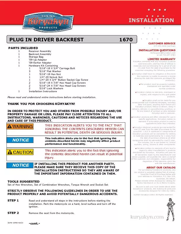
/
PARTS INCLUDED 1 Receiver Assembly  1 Backrest Assembly  1 Storage Bag PARTS INCLUDED 1 Receiver Assembly  1 Backrest Assembly  1 Storage Bag

PARTS INCLUDED 1 Receiver Assembly 1 Backrest Assembly 1 Storage Bag - PDF document

karlyn-bohler
karlyn-bohler . @karlyn-bohler
Follow
493 views
Uploaded On 2016-03-01

PARTS INCLUDED 1 Receiver Assembly 1 Backrest Assembly 1 Storage Bag - PPT Presentation

CUSTOMER SERVICE 8773703604 toll free INSTALLATION QUESTIONS techsupportkuryakyncom PLUG IN DRIVER BACKREST 1670 167023HD0213 THIS INDICATION ALERTS YOU TO THE FACT THAT This ID: 238019

CUSTOMER SERVICE 877.370.3604 (toll free)

Share:

Link:

Embed:

Download Presentation from below link

Download Pdf The PPT/PDF document "PARTS INCLUDED 1 Receiver Assembly 1 Ba..." is the property of its rightful owner. Permission is granted to download and print the materials on this web site for personal, non-commercial use only, and to display it on your personal computer provided you do not modify the materials and that you retain all copyright notices contained in the materials. By downloading content from our website, you accept the terms of this agreement.


Presentation Transcript

PARTS INCLUDED 1 Receiver Assembly 1 Backrest Assembly 1 Storage Bag 1 ‘09-Up Adapter 1 ‘08-Earlier Adapter 1 Hardware Kit Containing 1 5/16”-18 X 3/4” Carriage Bolt 3 5/16” Flat Washer 1 5/16”-18 Hex Nut 1 1/4”-20 Nylock Nut 1 1/4”-20 X 3/4” Button Socket Cap Screw 2 5/16”-18 X 7/8” Hex Head Cap Screws 2 5/16”-24 X 7/8” Hex Head Cap Screws 2 5/16” Lock Washers 1 Installation Instructions Please read and understand entire instructions before starting installation. THANK YOU FOR CHOOSING KRYAKYN! IN ORDER TO PROTECT YOU AND OTHERS FROM POSSIBLE INJURY AND/OR PROPERTY DAMAGE OR LOSS, PLEASE PAY CLOSE ATTENTION TO ALL CUSTOMER SERVICE 877.370.3604 (toll free) INSTALLATION QUESTIONS techsupport@kuryakyn.com PLUG IN DRIVER BACKREST 1670 1670-23HD-0213 THIS INDICATION ALERTS YOU TO THE FACT THAT This indication alerts you to the fact that ignoring the contents described herein may negatively affect product performance and functionality. This indication alerts you to the fact that ignoring the contents described herein can result in potential injury IF INSTALLING THIS PRODUCT FOR ANOTHER PARTY, PLEASE MAKE SURE THEY RECEIVE THIS COPY OF THE INSTALLATION INSTRUCTIONS SO THEY ARE AWARE OF THE IMPORTANT INFORMATION CONTAINED IN THEM. Avoid damage to the motorcycle. Protect painted surfaces with a soft cloth or blanket. STEP 3 Determine which mounting bracket adapter you will need for your bike. PIC 1 STEP 4 Using the included Carriage Bolt, washer and 5/16” hex nut, loosely install the bracket (determined in Step 3) to the receiver. PIC 2 Insert the carriage bolt from the underside of the receiver, through the adapter bracket. Use the flat washer and hex nut on top of the adapter bracket. STEP 5 On ‘99 and later bikes: Remove the two flange nuts from the studs in the rear fender. DO NOT remove the white plastic retaining washers from these studs, they will fall through the fender. PIC 3 Set these aside, they will be reused. On ‘98 and earlier bikes: Remove the two fasteners securing the handrail to the rear fender. Set these aside, they will not be reused. STEP 6On ‘09-Later bikes: Remove the two Torx screws holding the ECU to the frame. PIC 3 and PIC 4 Slide the adapter bracket under the tabs and reinstall the Torx screws. Tighten securely. On ‘08-Earlier Bikes: Attach the adapter bracket to the open hole in the frame brace behind the battery (PIC 5) by inserting the included button socket head cap screw through the bracket, through the frame brace and secure with the included 1/4”-20 nylock nut. Tighten securely. PIC 6 ADJUSTMENT AND INSTALLATIONKuryakyn’s Plug and Play Backrest is almost infinitely adjustable. This adjustability allows it to accommodate different seats and rider preferences. The following steps will allow you to tailor the four different adjustments (Receiver location, Backrest Pad location, Backrest Pad height and Receiver angle) of the Backrest to your requirements. Be aware, it may take a few trials to get the Backrest in your desired location. RECEIVER LOCATION STEP 7 Determine the location of the Receiver by choosing one of the four sets of holes in the base, then: On ‘99 and later bikes: Install the flange nuts from Step 5, to secure the receiver to the fender. PIC 6 Snug these and the hex nut on the adapter bracket for now. On ‘98 and earlier bikes: Determine from the fasteners removed in Step 5 if they are coarse or fine thread. Using the matching supplied 5/16” hex head cap screws, flat washers and lock washers, secure the receiver to the fender. PIC 6 Snug these and the hex nut on the adapter bracket for now. Not all mounting positions of the Receiver will be available on all models. The two middle holes are most commonly used.STEP 8 Replace the seat. AFTER INSTALLING THE SEAT, PULL UP ON IT TO ENSURE IT IS LOCKED INTO PLACE. A LOOSE SEAT CAN SHIFT AND CAUSE LOSS OF CONTROL RESULTING IN SERIOUS INJURY OR DEATH. PLUG IN DRIVERS BACKREST 09—LATER PIC 1 HEX NUT CARRIAGE BOLT FLAT WASHER PIC 3 REMOVE THESE NUTS DO NOT REMOVE THESE REMOVE THESE BOLTS 09-LATER PIC 4 BRACKET GOES UNDER ECU TABS 08-EARLIER PIC 5 USE THIS HOLE USE OEM FLANGE NUTS OR HEX BOLTS HERE BUTTON SOCKET CAP SCREW ADJUSTING HEIGHT AND POSITION OF THE BACKREST PAD STEP 9 Insert the backrest into the receiver. The backrest may be inserted in the forward or rearward position. To change the position, remove the pouch from the back of the backrest and rotate the backrest to the opposite side of the bar (PIC 7), replace the pouch. STEP 10 The Backrest post has six indents at different positions that will allow you to change the height of the pad. Simply pull up or push down on the backrest pad until you feel the intents click in the desired position. Once the indent is felt, the spring loaded pin in the receiver will keep the Backrest in this position. To increase the tension on the spring loaded pin, turn the set screw on the receiver inward (clockwise). To decrease the tension on the spring loaded pin, turn the set screw on the receiver outward (counter-clockwise). PIC 7 ADJUSTING THE ANGLE OF THE RECEIVER STEP 11 To fine tune the angle of the backrest, remove the seat. Use the hex nuts on the receiver (PIC 7): To tip the backrest further forward, turn the top hex nut counter-clockwise to move it away from the bushing. Turn the bottom hex nut counter-clockwise to tilt the receiver mount forward to the desired position. Turn the top hex nut clockwise against the bushing to lock the receiver in place. To tip the receiver further rearward, turn the bottom hex nut clockwise until the receiver is in the desired position, then turn the top hex nut clockwise to lock it into position. STEP 12 Once the Backrest is in the desired location, remove the seat. STEP 13On ‘99 and later bikes: Tighten the flange nuts from Step 7 and the hex nut on the adapter bracket securely. On ‘98 and earlier bikes: Tighten the hex head cap screws from Step 7 to 19 ft/lbs. tighten the hex nut on the adapter bracket securely. STEP 14 Replace the seat. Insert the Backrest pad. AFTER INSTALLING THE SEAT, PULL UP ON IT TO ENSURE IT IS LOCKED INTO PLACE. A LOOSE SEAT CAN SHIFT AND CAUSE LOSS OF CONTROL RESULTING IN SERIOUS INJURY OR DEATH. THIS BACKREST IS NOT MEANT TO BE USED AS A SAFETY RESTRAINING DEVICE. FAILURE TO HOLD ONTO THEMOTORCYCLE MAY RESULT IN SERIOUS INJURY OR DEATH. Ensure that the installation of this product does not interfere with the proper operation of the motorcycle before riding. It is the installer’s responsibility to ensure that all of the fasteners (including pre-assembled) are tightened before operation of the motorcycle. Küryakyn will not provide warranty coverage on products or components lost due to improper installation or lack of maintenance. Periodic inspection and maintenance are required on all fasteners. Ride On! PLUG IN DRIVERS BACKREST PIC 9 USE THESE HEX NUTS TO FINE TUNE POSITION OF BACKREST PIC 8 USE THIS SET SCREW TO ADJUST TENSION ON SPRING PIN PIC 7 REMOVE POUCH AND ROTATE BACKREST TO OPPOSITE SIDE OF BAR