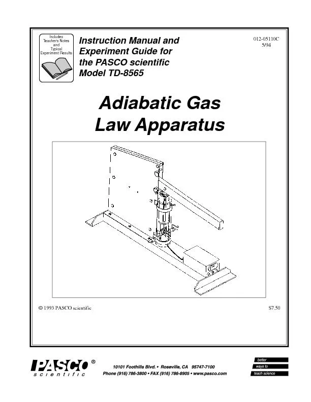
/
1993 pasco scientific 7 50adiabatic gaslaw apparatus 1993 pasco scientific 7 50adiabatic gaslaw apparatus

1993 pasco scientific 7 50adiabatic gaslaw apparatus - PDF document

kittie-lecroy
kittie-lecroy . @kittie-lecroy
Follow
357 views
Uploaded On 2016-05-08

1993 pasco scientific 7 50adiabatic gaslaw apparatus - PPT Presentation

01205110C the PASCO scientific Teachers NotesTypical Adiabatic Gas Law Apparatus i Table of ContentsSectionPageCopyright Warranty and Equipment Return ID: 311118

012-05110C the PASCO scientific Teacher's NotesTypical Adiabatic Gas

Share:

Link:

Embed:

Download Presentation from below link

Download Pdf The PPT/PDF document "1993 pasco scientific 7 50adiabatic gasl..." is the property of its rightful owner. Permission is granted to download and print the materials on this web site for personal, non-commercial use only, and to display it on your personal computer provided you do not modify the materials and that you retain all copyright notices contained in the materials. By downloading content from our website, you accept the terms of this agreement.


Presentation Transcript

012-05110C © 1993 PASCO scientific$7.50Adiabatic GasLaw Apparatus the PASCO scientific Teacher's NotesTypical Adiabatic Gas Law Apparatus i Table of ContentsSectionPageCopyright, Warranty and Equipment Return.......................................................iiEquipment Included.......................................................................................1Features..........................................................................................................1How to Use this Manual................................................................................1Theory..................................................................................................................2Description of Apparatus.....................................................................................3Using the TD-8565 with the PASCO Series 6500 Computer Interface........5IBM compatible computers...........................................................................5Apple II compatible computers.....................................................................7Expansion of a Gas........................................................................................7Measurement of Work to Compress Gases Adiabatically.............................9Equipment Needed:.................................................................................9Purpose....................................................................................................9Theory......................................................................................................9Procedure.................................................................................................9Graphs and Data Tables.........................................................................10Calculations...........................................................................................10Schematic...........................................................................................................11Specifications / Sample Data.............................................................................12Technical Support....................................................................Inside Back Cover Adiabatic Gas Law Apparatus012-05110C ii PleaseÑFeel free to duplicate this manualsubject to the copyright restrictions below. Copyright, Warranty and Equipment ReturnFAX:(916) 786-3292email:techsupp@pasco.comweb:www.pasco.com ä NOTE: NO EQUIPMENT WILL BEACCEPTED FOR RETURN WITHOUT ANAUTHORIZATION FROM PASCO. IntroductionThe PASCO Model TD-8565 Adiabatic Gas LawApparatus enables the user to investigate the compres-sion and expansion of gases.Sensitive transducers in the apparatus measure thepressure, temperature, and volume of the gas almostsimultaneously as the gas is compressed or expandedrapidly under near adiabatic conditions, or slowlyunder isothermal conditions. Analog signals from thesensors are monitored by the Series 6500 ComputerInterface, a three channel analog-to-digital dataacquisition system. The computer functions as a threechannel storage oscilloscope. In addition, the dataacquisiton program, Data Monitor, can plot graphs ofpressure, temperautre, and volume. It can plot a graphof pressure versus volume and integrate under thecurve to determine the work done on the gas.Equipment Included:The TD-8565 consists of the Adiabatic Gas LawApparatus and this instruction manual (part number012-05110). The apparatus comes with a permanentlyattached cable with a five pin DIN plug that carries thesignal from the volume transducer, and two DIN-plug-to-mini-phone-plug cables (part number 520-063) thatcarry the signals from the pressure and temperaturesensors.¥ Measure g, the ratio of specific heats for the gas(C¥ Measure the work done on the gas and compareit with the change in internal energy (CVDand also with the theoretical work performed.¥ Compare the final pressure and temperaturewith values predicted by the Adiabatic GasLaw.¥ Use monatomic, diatomic, and polyatomic gasesto determine the effects of molecular structureon g.¥ Investigate isothermal compression and expan-sion by performing the experiment slowly, inincremental steps.Other:¥ The Adiabatic Gas Law Apparatus can also beused with the MultiPurpose Lab Interface(MPLI) from Vernier Software.¥ The Apparatus can use a nine volt battery tosupply the excitation voltage for the bridge cir-cuits of the temperature and pressure sensors.You can also use an external 12 V, 10 mApower supply, but it must be a "floating ground"supply.How to Use this ManualThe first section of this manual describes the theoryof the adiabatic process and the operation of theapparatus. The next section describes the setup,calibration, and data collection procedure. The finalsection contains the experimental write-up, apparatusschematic and specifications. =T2V2g Another relationship to be examined in this experi-ment is the energy expended or work done on thegas while compressing it adiabatically. Equation 3,the Adiabatic Gas Law, states that: PV=k=P1V1g or=kVg work done to compress the gas is:Ä=PdVV1V2 =kdVVg V1V2 =kV 1± V1V2=P1V1g V 1± V1V2W=P1V1g V2 ±V1 When a process takes place without thermal energyentering or leaving the system it is an adiabaticprocess. This would occur if the system were per-fectly thermally insulated or if the process occurred sorapidly that there could be no heat transfer. Thefollowing is a derivation of the relationship of thepressure P, temperature T, and volume V when nmoles of a confined ideal gas are compressed orexpanded adiabatically.The first law of thermodynamics can be stated as:À=dT+pdVfor an adiabatic process where CV is the molarspecific heat at constant volume, T is the absolutetemperature, nvolume. For any ideal gas PV = nRT. ThusPdV + Vdp = nRdT. Solving for dT gives:Á=PdV n R +VdP n R Substituting equation 2 into equation 1 gives:dQ=PdVnR +VdPnR +PdVCvR +1 PdV+CvR VdP=Cv+R PdV+CvVdP=CPPdV+CvVdPwhere CP is the molar specific heat at constant pres-sure. CP is related to CV by CP = R. The ratioof CP to CV is denoted as g,(gamma). Using theseresults we obtain:CPPdVCvPV +dPP =0dVV +dPP +ln t Â=constan t P1V1g=P2V2gThis result is the standard adiabatic gas law.From equation 3 and the ideal gas law PV = nRT asecond form of the adiabatic gas law is: TheoryR = universal gas constant (approximately 8.314 J/moleûK. Description of Apparatus Figure 2, Cylinder As mentioned above, the electronic circuit consists ofthe two amplifiers with bridge excitation sources. Theelectronics may be powered with an external "floatingground" 10 V DC supply (current about 10 ma), or a9 volt battery. The negative input is notchassis ground. The sleeves of the output jacksare connected to chassis ground which is main-input. For this reason the supply voltage fromyour computer should not be used to power theequipment if the computer voltage source andinputs have a common ground.A transparent millimeter scale, Fig 2, item h, on thefront of the cylinder facilitates direct measurement ofin the computations or to calibrate the volume dataacquisition. Two removable pins, Fig 2, item i , areprovided to vary the excursion of the piston by limit-ing the motion of the piston lever. Holes to store thepins when not used are provided directly above thecentral label. Â: For some of the calculations only the ini-tial and final volumes are needed. These can bedetermined by reading the transparent scale locatedon the front of the cylinder. This indicates the dis-placement of the piston which when multiplied byof the piston is approximately 4.45 cm. For bestresults, measure the actual diameter. Since for somecalculations the ratios of volumes are used, the dis-placements can be used in the calculations insteadof the actual volumes.ä NOTE: A minor error in the volume mea-surement is caused by the port or opening in thegas cocks. Add one cubic centimeter to allvolume measurements or 0.06 cm to the piston 0.0050.00Time (milliseconds)Potential vs Time Temperature and Temperature Sensors vs time A:Volume: Hold the piston at the highest positionB:Temperature: Use the calibration equation pro- Ã C:Pressure: Hold the piston at a high position, and*The calibration information is on a card on the Figure: Oscilloscope Mode (MS-DOS version) ÅÆ Apple II compatible computersä NOTE: Operation with the Apple II series ofcomputers is severely limited by the speed of thecomputer. If there is any other computer you canuse rather than an Apple II, please do so.Àdescribed for the IBM. We do not recommend cali-brating the apparatus in SI units, since the round-off error introduced by the Apple will be greaterthan the volume of the cylinder in m3. ÁBecause of the input limitations of the Apple II, itis not possible to graph all three traces in oscillo-scope mode. Instead, choose "C" for fast data col-Enter the delay between data points as 1.0 ms, andcollect about 100 data points. (Actual delay be-tween readings on individual channels will be 3.0ms, since the computer alternates channels for eachreading.) Press the space bar when you are ready,simultaneously change the volume. The inputis not automatically triggered.®and choose ÒPÓ to plot the data. The best graphs areobtained when the inputs are uncalibrated; other-wise the difference in scales between data sets mayresult in only one of the lines being visible.Expansion of a GasTo perform a qualitative demonstration of the adiabaticClamp the front foot of the apparatus base to the table.Fill the cylinder to maximum displacement at atmo-spheric pressure. Close the gas cock and compress thegas. Set the trigger level to a value slightly higher thanthe steady value and set the slope to positive or "goingup". When ready to take data, compress the gas to thisinitial volume, hold it there until equilibrium isachieved (about 30 seconds), press "S" for SingleSweep, and then very rapidly expand the gas fully.friction in the cylinder, but the part of the cylinder thatbecomes warm is not in contact with the gas. How-ever, when expanding the gas, the part of the cylinderthat is warmed is in contact with the gas. For thisreason, the expansion data does not give good quanti-tative results. Figure: Graph of Voltage vs. time (Apple II version) ) a.Connect the gas supply to one of the gas cocks.b.Remove the piston excursion limit pins so the range of volumes is maximumc.With the piston down and the second gas cock closed, fill the cylinder to maximumd.Now shut the incoming gas cock off and exhaust through the second gas cock.e.Close the exhaust cock and re-fill with gas. Experiment:Measurement of Work to Compress Operating Voltage:9-15 volts DC or 9 volt battery. Higher voltage willprovide capability of increased range in temperatureand pressure measurements. A floating power supplyis required.Operating Current:10-12 mA.Temperature Measurement:±2 KPressure Measurement:±2 kPaDIN connector pin configuration: (Pins pointed atVolume Cable (flat)Pressure and Temperature Cables (grey)ä: The Adiabatic Gas Law apparatusoperates ideally with a 12 V DC floating externalsupply. However, for most measurements it willoperate satisfactorily with a 9 volt battery. If thesupply voltage is low or the signals very large,either the pressure or temperature signal ampli-If this occurs either increase the operatingvoltage or decrease the compression ratio in theexperiment which will reduce the output signal Signal V in Signal V in Sample DataData taken with an IBM PC and a PASCO Series 6500 [[[[[[[[[[[[[[[[[[[[[[[[[[[[[[[[[[[[[[[[[[[[[[[[[[[[[[[[[[[[[[[[[[[[[[[[[[[[[[[[[[[[[[[[[[[[[[[[[[[[[[[[[[[[[[[[[[[[[[[[[[[05000010000015000020000025000030000035000000.000050.00010.000150.00020.00025Volume (m^3) [[[[[[[[[[[[[[[[[[[[[[[[[[[[[[[[[[[[[[[[[[[[[[[[[[[[[[[[[[[[[[[[[[[[[[[[[[[[[[[[[[[[[[[[[[[[[[[[[[[[[[[[[[[[[[[[[[[[[[[[[[[10000010000000.00010.001Volume (m^3) 012-05110CAdiabatic Gas Law Apparatus 13 Technical Support 012-05110CAdiabatic Gas Law Apparatus Adiabatic Gas Law Apparatus