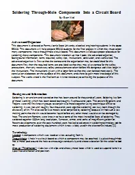
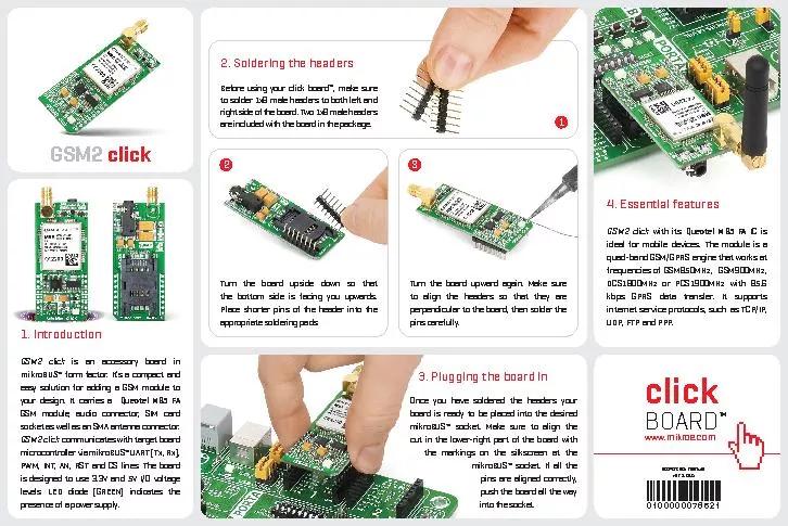
PDF-2. Soldering the headersOnce you have soldered the headers your board

Author : kittie-lecroy | Published Date : 2016-05-06

2 3 1 is an accessory board in form factor It146s a compact and easy solution for adding a GSM module to your design It carries a Quectel M95 FAGSM module audio

Presentation Embed Code

Download Presentation

Download Presentation The PPT/PDF document "2. Soldering the headersOnce you have so..." is the property of its rightful owner. Permission is granted to download and print the materials on this website for personal, non-commercial use only, and to display it on your personal computer provided you do not modify the materials and that you retain all copyright notices contained in the materials. By downloading content from our website, you accept the terms of this agreement.

2. Soldering the headersOnce you have soldered the headers your board: Transcript


2 3 1 is an accessory board in form factor It146s a compact and easy solution for adding a GSM module to your design It carries a Quectel M95 FAGSM module audio connector SIM card socket as. square 0.5 mm, angled Parameters of article SLY 3 035 version standard no. of contacts 1 - 50 surface goldplated angle angled number of rows 1 connection type soldering grid By: Evan . Wall. Advanced Organizer. This document is directed at Pennsylvania State University electrical engineering students in the course EE210. This document will help prepare EE210 students for the final project in which they must solder many components into a through-hole circuit board. This document will discuss proper procedure for soldering these components. This document is broken up into 4 parts; the advanced organizer, Background information, Items required, safety tips, instructions, conclusion, and works cited. The advanced organizer is first so that the context and the organization may be established for this document first, then the required items are provided so that they may give context for the safety precautions, then any necessary safety precautions are taken before the dangerous activities begin in the instructions. Intro . to Soldering. Dr. Robert Ross. Overview . (what you should learn today). What are Printed Circuit Board (PCB’s). How PCB are made. Different types of PCBs. What is soldering. How to solder. Soldering Tips. Soldering is a process in which two or more metal items are joined together by melting and flowing a filler metal into the joint, the filler metal having a lower melting point than the workpiece. . “. Surface Mount Soldering” . Nick Carter12/02/2016. This was taught . at Nova Labs by . Bob . Coggeshall. nova-labs.org. Meetup Nova-Makers Reston. .. See notes page for this ppt. application.. . Request/ Response Messages . GET /announce.html HTTP/1.0. Host: www.joes-hardware.com. HTTP/1.0 200 OK. Content-Type: text/plain. Content-Length:19. Hi! I’m a message. Request. Response. Client. Server. Soldering Iron. Soldering Iron Care & Maintenance. Tinning Process. Good Solder Connections. Bad Solder Connections. De-Solder Process: Solder Sucker. Soldering Safety. Soldering Tools. Vise. Safety glasses. Magic of Electrons . Soldering. Soldering Tools. Soldering Iron. Soldering Iron Care & Maintenance. Tinning Process. Good Solder Connections. Bad Solder Connections. De-Solder Process: Solder Sucker. Soldering & De-soldering. 2. This presentation will…. Review the tools needed to solder and de-solder electronic components.. Demonstrate how to . tin. a soldering iron tip.. Demonstrate the soldering process.. Soldering is a process in which two or more metal items are joined together by melting and flowing a filler metal into the joint, the filler metal having a lower melting point than the workpiece. . soldering iron solder parts to solder soldered parts. Magic of Electrons . Soldering. Soldering Tools. Soldering Iron. Soldering Iron Care & Maintenance. Tinning Process. Good Solder Connections. Bad Solder Connections. De-Solder Process: Solder Sucker. S.R.Norr. , UMD. Definition: Soldering. A process in which two or more items (usually metal) are joined together by melting and putting a filler metal (. solder. ) into the joint, the filler metal having a lower melting point than the adjoining metal. The intent is to create a strong MECHANICAL joint. © 2014 Project Lead The Way, Inc.. Digital Electronics. Soldering & De-soldering. 2. This presentation will…. Review the tools needed to solder and de-solder electronic components.. Demonstrate how to . PRESSEMELDUNGIPRESS RELEASESEHO Systems GmbH I Frankenstr 7 -11 I97892 Kreuzwertheim I49 0 93 42 / 889-0 I infosehode1Kontakt IContactHeike Schlessmann Tel 49 0 93 42 / 889-220 heikeschlessmannsehod

Download Document

Here is the link to download the presentation.
"2. Soldering the headersOnce you have soldered the headers your board"The content belongs to its owner. You may download and print it for personal use, without modification, and keep all copyright notices. By downloading, you agree to these terms.

Related Documents