/
Renishaw plcNew Mills, Wotton-under-Edge,uk@renishaw.comwww.renishaw.c Renishaw plcNew Mills, Wotton-under-Edge,uk@renishaw.comwww.renishaw.c

Renishaw plcNew Mills, Wotton-under-Edge,uk@renishaw.comwww.renishaw.c - PDF document

kittie-lecroy
kittie-lecroy . @kittie-lecroy
Follow
370 views
Uploaded On 2015-11-03

Renishaw plcNew Mills, Wotton-under-Edge,uk@renishaw.comwww.renishaw.c - PPT Presentation

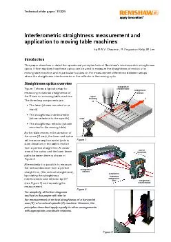
ConclusionThis paper has explained in detail the operating principles behind interferometric straightness measurements It has also demonstrated how the operation of a straightness interferometer W ID: 181509

ConclusionThis paper has explained

Share:

Link:

Embed:

Download Presentation from below link

Download Pdf The PPT/PDF document "Renishaw plcNew Mills, Wotton-under-Edge..." is the property of its rightful owner. Permission is granted to download and print the materials on this web site for personal, non-commercial use only, and to display it on your personal computer provided you do not modify the materials and that you retain all copyright notices contained in the materials. By downloading content from our website, you accept the terms of this agreement.


Presentation Transcript

Renishaw plcNew Mills, Wotton-under-Edge,uk@renishaw.comwww.renishaw.comIssued: 0413 Part no. H-5650-2046-01-A©2013 Renishaw plc. All rights reserved.Renishaw reserves the right to change specifications without noticeRENISHAW and the probe symbol used in the RENISHAW logo are registered trade marks of Renishaw plc in the United Kingdom and other countries. apply innovation and names and designations of other Renishaw products and technologies are trade marks of Renishaw plc or its subsidiaries. All other brand names and product names used in this document are trade names, trade marks or registered trade marks of their respective owners.RENISHAW HAS MADE CONSIDERABLE EFFORTS TO ENSURE THE CONTENT OF THIS DOCUMENT IS CORRECT AT THE DATE OF PUBLICATION BUT MAKES NO WARRANTIES OR REPRESENTATIONS REGARDING THE CONTENT. RENISHAW EXCLUDES LIABILITY, HOWSOEVER ARISING, FOR ANY INACCURACIES IN THIS DOCUMENT.For worldwide contact details, please visit our main website at www.renishaw.com/contactAbout RenishawRenishaw is an established world leader in engineering technologies, with a strong history of innovation in product development and manufacturing. Since its formation in 1973, the company has supplied leading-edge products that increase process productivity, improve product quality and deliver cost-effective automation solutions.A worldwide network of subsidiary companies and distributors provides exceptional service and support for its customers.Products include:Additive manufacturing, vacuum casting, and injection moulding technologies for design, prototyping, and production applicationsDental CAD/CAM scanning and milling systems and supply of dental structuresFixturing for CMMs (co-ordinate measuring machines) and gauging systemsHigh speed laser measurement and surveying systems for use in extreme environments ConclusionThis paper has explained, in detail, the operating principles behind interferometric straightness measurements. It has also demonstrated how the operation of a straightness interferometer (Wollaston prism) can be compared to an indicator and how the straightness reector can be compared to a precision straight edge and why the laser’s position is less critical. This analogy has then been used to explain the important differences between setups on a moving table machine. It has demonstrated that in order to correctly assess the straightness of movement of the cutting tool relative to the work-piece the straightness interferometer (or indicator) should be attached to the tool holder, and the straightness reector (or straight edge) should be xed to the work holder (moving table) as described in Set-up A and recommended in ASME B5.54. Whereas Set-up B (moving interferometer), is more suited to assessing the underlying quality of machine construction and fault diagnosis.Whatever the choice of measurement set-up the following tips will help optimise the accuracy of Tips for accurate interferometric straightness measurementIn order to maximise the accuracy of measurement when using a straightness interferometer the following are recommended.Always use short range straightness optics if the axis is short enough to allow this. Short range optics are more accurate than long range optics and are less sensitive to environmental effects.Minimise the effects of air turbulence induced noise. As pockets of slightly warmer or colder air meander through the laser beams they temporarily alter the optical path lengths creating noise on the straightness readings. The noise maybe reduced by enabling long term averaging in the laser software and altering the local environment.RemoveAlternatively stir the air vigorously using fans, this will help homogenise the air and also the frequency of any noise is increased and so will be more effectively removed by long term averaging. Figure 25 shows an example of the reduction in air turbulence induced noise using a fan to blow air across the beams.Avoid excessive slope error by adjusting the straightness reector; this is particularly important on manual machines.Ensure the reector is securely mounted and thermally stabilised. Remember the reector generates a virtual straight edge in space that may extend for many metres. Instability in the angle of the reector due to thermal or vibration effects should be avoided. It may be benecial to cover the reector housing with a cloth to insulate it from thermal changes in the environment.Ensure the straightness interferometer is accurately roll aligned to the reector. This ensures the straightness measurements are not affected by small changes in the angular alignment of the laser to the optics. Particular care is needed at the shorter ranges where simply ensuring the returned beams are accurately overlapped may not be sufcient if there are concerns over the angular stability of the laser mounting or of the machine itself (e.g. anti-vibration mounted machines or poor foundations). If concerns remain, consider rigidly attaching the laser to the machine. Figure 2511 Fan Moving interferometer or moving reector - Which is “Right”?In order to answer this, consider a part containing a row of ve equal size, equal depth holes along the X axis as shown in section in Figure 24. The part is then placed on a Co-ordinate Measuring Machine (CMM) to check the accuracy of the holes. The CMM will show that all lies on a straight line. It will also show that the angle of each hole is different.So, from a work-piece viewpoint the X axis appears to be straight and only has a pitch error. This agrees with the laser straightness results obtained with the reector xed to the moving table and the indicator results obtained with a straight edge xed to the moving table.This observation, and the analogy with an indicator and straight edge, provides a valuable insight into whether the straightness interferometer or reector should be xed to the moving table.Set-up A (xed interferometer or indicator) - In general this set-up should be used when checking the accuracy of the relative movement between the work-holder and spindle. This arrangement gives an insight into the accuracy of the parts the machine will produce as it shows the errors in spindle positioning relative to the work-piece’s coordinate system. This set-up is recommended in ASME B5.54 when checking moving table machines.Set-up B (xed reector or straight edge) - In general this set-up should be used when checking for errors in motion of a single point on the machine. For example to trace the trajectory of a particular point on the moving table versus the machine’s coordinates system. This gives information on the quality of construction of the machine, but not necessarily about how accurately it will make parts. Figure 24 02004006008001000VerticalStraightnesspointedfitted) Figure 2310 Again the results graph from this setup indicates that the table motion is straight. The reason for this is that the vertical distance from the spindle to the table mounted straightedge remains constant as the table moves underneath.The laser straightness results with a moving reector agree with those obtained by indicating a straight edge mounted on the moving table.Now consider what happens if the components are swapped over and the interferometer (or the indicator) is mounted on the moving table, as in Set-up B.Set-up B (moving interferometer or indicator)Figure 22 shows a tripod mounted laser, a spindle mounted reector and the interferometer attached to the moving table. The straightness graph produced by this set-up indicates that the motion is curved. This is clearly a very different result to that obtained when the reector was the moving optic.Finally consider what happens if the laser system is replaced with a straight edge mounted to the spindle and a digital indicator mounted to the moving table, as shown in Figure 23 (below).Again the results graph from this setup indicates that the motion is curved.The laser straightness results with a moving interferometer agree with those obtained from a straight edge mounted on the spindle with an indicator mounted on the moving table. The results obtained with a moving straightness interferometer (or indicator) are clearly very different to those obtained with a moving reector (or straight edge). But which results are “right”? 02004006008001000VerticalStraightnesspointedfitted) Figure 229 Initially this may seem like an inaccurate result, since the machine table is clearly moving along a curved path, whereas the straightness graph shows a straight line. This is discussed in more detail later.Now consider what happens if the laser system is replaced with a straight edge mounted on the moving table and a digital indicator mounted to the spindle, as shown in Figure 21 (below). 02004006008001000VerticalStraightnesspointedfitted) Figure 20Figure 21 02004006008001000VerticalStraightnesspointedfitted) 8 However, modelling of various combinations of alignment errors shows that, if the Wollaston prism is not accurately aligned in roll (about the X axis), relative to the straightness reector, then there is some sensitivity to yaw (rotation about Z axis) of the laser (see Figure 19). Modelling shows that if the Wollaston prism is roll misaligned to the reector by radians, and the laser then yaws by radians, with a separation between the optics of L metres, the change in straightness reading (in metres) is L.. The same equation applies to both short and long range straightness optics.Changing measuring units shows that, if the Wollaston prism is roll misaligned to the reector by degrees, and the laser yaws by arc-seconds, with a separation between the optics of L metres, then the change in straightness reading in micrometres is approximately L./11.818. For example:If the Wollaston prism is misaligned to the reector by 1° in roll and the optics are 1m apart, then straightness reading of 0.846 micrometres.It is therefore advisable to take care to ensure the Wollaston prism and straightness reector are accurately aligned in roll before measurement starts. Once this is done then the straightness reading will not be signicantly affected by small changes in the alignment of the laser relative to the optics. The interferometric straightness reading can then be considered as depending solely on the relative positions of straightness reector (the straight-edge) and the straightness interferometer (the indicator). Note that this is quite different to the behaviour of non-interferometric laser based straightness measurements, where maintaining the pointing stability of the laser source is absolutely essentialStraightness measurements on moving table machinesThis paper will now consider the differences between measuring vertical straightness of the X axis of a vertical spindle machine tool, using two different setups (A and B) with either a laser interferometer system or an indicator and straight edge. These differences are highlighted by specically considering a moving table machine which has an X axis with a pitch error which is caused by the shifting weight of the table. The example assumes that the table casting behaves as a rigid body and that all the exing occurs within the underlying supporting guide-ways and bearings. For clarity, the amount of pitch error has been grossly exaggerated in the following gures. - with the straightness interferometer (or indicator) xed to the stationary spindle and reector (or straight edge) xed to the moving table (see Figures 20 and 21). - with the straightness reector (or straight edge) xed to the stationary spindle and interferometer (or indicator) xed to the moving table (see Figure 22 and 23).Set-up A (xed interferometer or indicator)Figure 20 (below) shows a tripod mounted laser, a spindle mounted straightness interferometer and a straightness reector attached to the moving table. The graph shows the straightness results produced by this set-up which indicate that the motion is straight. The reason for this is that the virtual straight edge produced by the reector intersects the straightness interferometer at a consistent position as the X axis moves because the change in the angle of the reector is compensated by the increasing separation from the interferometer. ReflectorInterferometer Laser Yaw Roll Figure 197 Wollaston prism is again moved in a perfectly straight line in the X direction, but this time the straightness reector is slightly misaligned by a small angle , as shown (grossly exaggerated) in Figure 16. If L is the distance moved, the laser straightness reading will change by ). Note that the indicator reading will be affected in exactly the same way if the straight edge is misaligned by the same amount. In straightness measurement, if the reector or straight edge is misaligned to the axis of travel, a “slope error” is introduced onto the measurements. This error is usually removed in software by end point or least squares tting to the data. However, it is wise to minimise the slope error (by adjusting the straight edge or the reector) to reduce sensitivity to errors of positioning in the X direction and, in the case of the laser, to ensure maximum signal is maintained along the axis.Effect of laser alignmentThe analysis so far has focussed on the operation of the straightness interferometer and reector and has drawn close parallels with the operation of an indicator and straight-edge. However, the laser interferometer measurements include a third component, the laser. Detailed analysis has been carried out to determine relative importance of the laser’s position and the effect of any misalignments on straightness measurements.Firstly consider the simple case of moving the laser in the Z- direction by a distance S, as shown in Figure 17. The laser beams have moved downwards across the interferometer by a distance S, in exactly the same way as when the interferometer was moved upwards by a distance S (see Figure 13). So, as before, this movement will introduce a relative change in beam lengths between Arm 1 and Arm 2, in the vicinity of the interferometer-4.S.sin(). But, the laser beams have also moved downwards across the reector by a distance S, in exactly the same way as when the reector was moved upwards by a distance S (see Figure 5). So, this movement will introduce a additional relative change in beam lengths, , of +4.S.sin(). These two changes are equal and opposite and so exactly cancel. Therefore pure translation of the laser head produces no change in the laser straightness readingis pitched by a small angle (as shown exaggerated in Figure 18) is less obvious and so detailed optical modelling was carried out to investigate this further. The results show that the difference in optical path lengths between Arm 1 and Arm 2 (and hence the resultant straightness reading) are not signicantly altered by small angular movements in pitch of the laser Figure 16 ReflectorInterferometerLaser Reflector InterferometerLaser Figure 17Figure 186 ReflectorInterferometerLaser Straig Finally, when the beams emerge from the third wedge, back into air, they both experience a decrease in refractive index and so are both deviated further away from the normal and their divergence is increased still further. Straightness optics are manufactured to tight tolerances such that the beam divergence angle (2) between the beams emerging from the Wollaston prism matches the effective angle of the straightness reector, within a few arcseconds.The differential refraction within the Wollaston prism, which causes the beams to diverge, is also the reason why the optic can be used to measure straightness. Consider what happens if the Wollaston prism is moved a distance S, in the Z direction to a new position as indicated by the dotted lines in Figure 13. It is clear that the upper (vertically polarised) beam will pass through more material which it sees as having lower refractive index (L), whereas the lower (horizontally polarised) beam will pass through more material which it sees as having the refractive index (H), altering their optical path lengths accordingly. Because the gradient in optical path length across the Wollaston is also responsible for producing the beam divergence angle of 2, it can easily be shown that moving the Wollaston sideways by a distance S will the optical path length of the upper beam (which forms Arm 1 of the interferometric measurement) by 2.S.sin( the optical path length of the lower beam (which forms Arm 2 of the interferometric measurement) by 2.S.sin(). Thus making a total relative change in beam lengths between Arm 1 and Arm 2 of -4.S.sin(). The laser system software will convert this relative change in path lengths into a straightness reading by dividing by 4.sin() to give a non-straightness reading of -S. is exactly the same result as when the straightness reector was moved sideways by a distance S (see Figure 5) except the sign convention is inverted.Now consider what happens if the Wollaston is tipped, by a small angle about its geometric centre, (as shown exaggerated for clarity in Figure 14). Detailed optical modelling of the beam paths through the system reveals that the difference in optical path lengths between Arm 1 and Arm 2 (and hence the resultant straightness reading) are not signicantly altered by small angular movements of the Wollaston prism. This again matches the analogy of the straightness interferometer acting like an indicator, (which would also not be affected by small changes in angle).Figure 15 illustrates what happens if the Wollaston prism is moved in a perfectly straight line, in the X direction, (as indicated by the yellow arrow and dotted new position lines). The laser beams in both Arm 1 and Arm 2 will increase in length by the same amount and so the laser straightness measurement will not change. This again matches the behaviour of an indicator moving along an aligned straight edge. Cirbeam Figure 13 Reflector Laser Interferometer Straig Figure 14Figure 15 5 ReflectorInterferometerLaser Straig Although more complex this design has some advantages over a simple two mirror design.The retro-reecting design ensures outward and return beams don’t overlap, making it easier to trace their paths during beam alignment.The retro-reecting action also means that accurate roll alignment of the reector about its long axis is not required as retro-reecting action will ensure the beams are returned to the interferometer. Again this makes beam alignment easier.The use of a solid block of glass ensures dimensional stability and mechanical robustness.Detailed optical modelling shows that if the solid reector is tipped by a small angle that is a distance L from the interferometer (as in Figure 7), the straightness reading is still altered by ) as described earlier. So the more complex solid glass block straightness reector design can still be imagined as generating a virtual straight-edge in space along its centreline, as described earlier.The straightness interferometer - a closer lookThe straightness interferometer (also referred to as a Wollaston prism) is made from 3 wedges of birefringent crystal, as shown in Figure 11. Unlike isotropic materials, which have a constant refractive index, birefringent materials have a refractive index that varies according to the orientation of their crystal axes and the polarisation of the light travelling through them. Light is transmitted through such material as two linear polarisations oriented parallel and perpendicular to the crystal’s optic axis. One polarisation will see a slightly higher refractive index and will travel more slowly, whilst the other will see a lower refractive index and will travel more quickly. The optic axes of the two outer wedges of the crystal are oriented vertically and the optic axis of the inner wedge is oriented horizontally, (as indicated by the double-headed arrows in Figure 11)Figure 12 shows the beam paths within the Wollaston prism. Note that for clarity the circularly polarised input beam is shown split into two separate beams (normally they would be overlapped) and the beam divergence angles have been exaggerated.As soon as the circularly polarised laser beam hits the rst wedge of birefringent material it is split into two linearly polarised beams, one is vertically polarised (i.e. polarised parallel to the crystal axis of the rst wedge). The other is horizontally polarised (i.e. polarised perpendicular to the crystal axis of the rst wedge). Due to the birefringent nature of the material, the vertically polarised beam will see a slightly higher refractive index (H) than the horizontally polarised beam, which sees a slightly lower refractive index (L), as shown in the Figure. Both beams travel in the same direction through the rst wedge.When the vertically polarised (upper) beam reaches the interface between the rst and second wedges, it experiences a in refractive index and so is refracted away from the normal. However, when the horizontally polarised (lower) beam reaches the same interface, it experiences in refractive index and so is refracted towards the normal. So this is the point where the beams start to take diverging paths.When the vertically polarised beam reaches the interface between the second and third wedges, it experiences an in refractive index and so this time is refracted towards the normal. Similarly, when the horizontally polarised beam reaches the same interface, it experiences a refractive index and so this time is refracted away from the normal. Because the interface between the second and third wedges slopes in the opposite direction to interface between the rst and second wedges, the beam divergence is further increased. Figure 11Figure 12 rtically beamHorizontallbeamCirbeam 4 The observation that the straightness reading appears to be “contaminated” by leads to the belief that the straightness reector must always be the stationary optic. However, this is not the case as there are times where this effect can be used to advantage.Consider, by analogy, the use of an indicator and precision straight edge (see Figure 7). The straightness reector and straight edge behave in a similar way. If either is moved in the Z direction, the movement directly. If the reector is pitched by a small angle the interferometer, the straightness reading is altered by L.tan(). In the same way, if the straight edge is pitched by an angle about a point that is a distance L from the tip of an indicator, the indicator reading also changes by L.tan(). Thus the straightness interferometer can be imagined as being equivalent to an indicator, and the straightness reector can be imagined as being equivalent to a precision straight edge. The straightness reector effectively generates a virtual straight edge in space, along its centreline. Deviations from this virtual straight edge are then “indicated” by the straightness interferometer. This powerful analogy (shown visually in Figure 8) is useful when deciding which straightness optic should be moving and which should be stationary. This is considered in more detail later. The straightness reector - a closer lookA simple straightness reector, as shown schematically in Figures 4 - 7, could be made from two at mirrors set at an angle to one another. However, Figures 1-3 indicate that Renishaw’s design is more complex. It is made from a solid block of glass, as shown in Figure 9, and utilises two refracting surfaces and two reecting surfaces. (Note the apex angle has been altered for clarity. In reality this angle is close to 177° on a short range straightness reector). Figure 10 shows the beam paths adjacent to and inside the reector. As the laser beam enters the glass it is refracted towards the normal by the increase in refractive index. It is then retro-reected by two reecting surfaces at 90° before nally being refracted away from the normal by the decrease in refractive index as it leaves the glass. ReflectorInterferometerLaser Straight edge Figure 7 ReflectorStraight edge Interferometer Figure 8Figure 9Figure 10 FrontviewviewTopview Reflecting ace RefractingaceRefractingace Reflectingace FrontviewviewTopview RefractionRefraction 3 It is easiest to understand how the system measures straightness by rstly considering what happens if the reector is the moving optic as shown in the simplied view in Figure 4. When the beam from the laser head reaches the straightness interferometer it is split into two separate beams with a divergence angle of 2tween them. (How this happens is described later in the section entitled “The straightness interferometer - a closer look”). These two beams travel to the straightness reector where they are reected back the way they came (this is described later in the section entitled “straightness reector - a closer look”). When they return to the straightness interferometer they are recombined and travel back to the laser head where they interfere to produce a measurement signal. The laser system measures the non-straightness by detecting relative changes between the optical path lengths in the two “arms” of the interferometer.If the straightness reector moves away from the interferometer along a perfectly straight line, in the X direction, (as indicated by the yellow arrow and dotted new position lines in Figure 4), then the laser beams in both Arm 1 and Arm 2 will increase in length by the same amount, and so the laser straightness measurement will not change. If however the straightness reector moves in the Z direction, by a distance S, (as indicated by the yellow arrow and dotted beam in Arm 1 will get longer by 2.S.sin(as it travels back and forth from the reector, and the beam in Arm 2 will get shorter by 2.S.sin(). Thus making a relative change in lengths between Arm 1 and Arm 2 of 4.S.sin(). In straightness mode the laser system software converts the relative change in path lengths, detected by the laser, into a straightness reading by dividing by 4.sin() to give a vertical straightness reading of S. The value of according to the straightness optics in use (Long or Short range).Now consider what happens if the , as shown in Figure 6. (Note that the angle has been grossly exaggerated for clarity). Here again the beam lengths in Arms 1 and 2 have changed relative to one another. by a pitch error in a moving linear path length in Arm 1 has become shorter by about 2.L.sin(where L is the separation between the optics. The beam path length in Arm 2 has become longer by 2.L.sin(), giving a total relative path length change between Arms 1 and 2 of 4.L.sin(). So, when the laser system software divides this relative path length change by 4.sin(), it will produce a non-straightness reading of L.tan(). Therefore, if the angle of the straightness reector is changed, the straightness reading is altered. Figure 4Figure 5 ReflectorInterferometerLaser ReflectorInterferometerLaser Figure 62 ReflectorInterferometerLaser Interferometric straightness measurement and application to moving table machinesby M.A.V. Chapman, R. Fergusson-Kelly, W. LeeIntroductions paper describes in detail the operational principles behind Renishaw’s interferometric straightness optics. It then explains how these optics can be used to measure the straightness of motion of a moving table machine and in particular focuses on the measurement differences between setwhere the straightness interferometer or the reector is the moving optic.Straightness optics overviewe 1 shows a typical setup for measuring horizontal straightness of the X axis on a moving table machine. The three key components are:The laser (shown mounted on a tripod)The straightness interferometer (shown attached to the spindle)The straightness reector (shown mounted to the moving table)As the table moves in the direction of the arrow (X axis), the laser and optics will measure any horizontal (side to side) deviation in the table’s motion from a perfect straight-line. A closer view of the optics and the laser beam paths between them is shown in Alternatively it is possible to measure the vertical deviation from a perfect straight-line, (the vertical straightness), by rotating the straightness interferometer and reector by 90° For simplicity, all further diagrams and text in this paper will refer to the measurement of vertical straightness of a horizontal axis (X), of a vertical spindle (Z) machine. However, the principles described apply equally to other arrangements with appropriate coordinate rotations. Figure 3 movementStraightness straightness Straightness interferometer Straightness Straightness interferometer Technical white paper: TE325