/
SHU MINAKUCHI, Y. Okabe, N. Takeda SHU MINAKUCHI, Y. Okabe, N. Takeda

SHU MINAKUCHI, Y. Okabe, N. Takeda - PDF document

kittie-lecroy
kittie-lecroy . @kittie-lecroy
Follow
468 views
Uploaded On 2016-02-23

SHU MINAKUCHI, Y. Okabe, N. Takeda - PPT Presentation

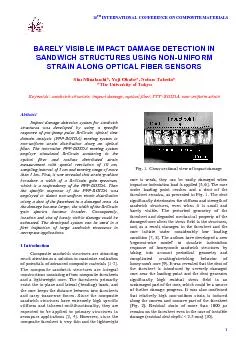
a Uniform strain b Nonuniform strain Fig 6 Response of PPPBOTDA to BGS has only one sharp narrow peak Fig 6 a When the nonuniform strain is introduced on t ID: 228608

Share:

Link:

Embed:

Download Presentation from below link

Download Pdf The PPT/PDF document "SHU MINAKUCHI, Y. Okabe, N. Takeda" is the property of its rightful owner. Permission is granted to download and print the materials on this web site for personal, non-commercial use only, and to display it on your personal computer provided you do not modify the materials and that you retain all copyright notices contained in the materials. By downloading content from our website, you accept the terms of this agreement.


Presentation Transcript

SHU MINAKUCHI, Y. Okabe, N. Takeda (a) Uniform strain (b) Non-uniform strain Fig. 6. Response of PPP-BOTDA to BGS has only one sharp narrow peak (Fig. 6 (a)). When the non-uniform strain is introduced, on the other hand, the Brillouin frequency also becomes non-uniform, since the Brillouin frequency at each point on the optical fiber is determined by the strain at the point. As a result, the BGS consisting of the entire Brillouin scattering along the spatial resolution becomes broad, as illustrated in Fig. 6. Moreover, the width of the BGS changes corresponding to the non-uniformity of the strain distribution. As explained above, the PPP-BOTDA sensing system not only realizes distributed strain measurement with spatial resolution of 10 cm, but also responds to the non-uniform strain within the spatial resolution. In the following sessions, new impact damage detection system for large sandwich structures using the specific response of the PPP-BOTDA is proposed and validated through an indentation damage detection test. 3 Impact damage detection system A schematic of the proposed system is illustrated in Fig. 7. The optical fibers are embedded Fig. 8. Damage detection procedure using distribution of BGS width in the adhesive layer between the facesheet and the core in a reticular pattern [3, 14]. Since the PPP-BOTDA has very long sensing range� ( 1 km), a limited number of the optical fibers are sufficient to cover the whole structure. When the impact damage is introduced, the residual dent of the facesheet induces tensile and compressive strain along the optical fiber at the concave and convex part. Consequently, the non-uniform strain broadens the width of the BGS obtained from the damaged area. Moreover, the width of the BGS broadens corresponding to impact damage size, since larger impact damage generates higher and wider non-uniform strain distribution along the residual dent of the facesheet (Fig. 2). Damage detection procedure is specifically presented in Fig. 8. First, the Brillouin gain spectra are measured throughout the optical fiber embedded Fig. 7. Schematic of impact damage detection system for sandwich structures BARELY VISIBLE IMPACT DAMAGE DETECTION IN SANDWICH STRUCTURE S USING NON-UNIFORM STRAIN ALONG OPTICAL FIBER SENSOR S in the whole structure or the area where the impact damage is suspected to be induced. Secondly, the width of each spectrum is calculated. Now, a full width at -1 dB from maximum (illustrated in Fig. 8) is selected as a representative value for the width of the BGS. When the impact damage is introduced, only the damaged area has unusually large value of , depending on extent of damage. Hence, damage location and size can be roughly estimated from the distribution of along the optical fiber. This proposed system must be useful in first inspection of impact damage in large sandwich structures. In the next section, the validity of the proposed system is confirmed by detecting barely visible damage in a honeycomb sandwich panel. 4.1 Materials and methods A schematic of the specimen is illustrated in Fig. 9. The sandwich panel consisted of CFRP facesheets (T700S/2500, Toray Industry, Inc., [0/90], thickness of 1.5 mm), aluminum honeycomb core (AL 1/4-5052-.001, Showa Aircraft Industry Co.) and thermoplastic adhesive films (AF-163-2K, 3M Co.). A single optical fiber was embedded between the preliminary molded upper facesheet and the adhesive layer. The upper facesheet was manufactured a little larger than the core and the lower facesheet for handling of the optical fiber. The experimental set-up is shown in Fig. 10. A hemispherical steel indenter, whose diameter was 12.7 mm, was attached to a material Fig. 9. Schematic of specimen for indentation damage detection test Fig. 10. Experimental set-up for indentation loading and BGS measurement testing system (AG-50kNI, Shimazu Co.) and a quasi static point load was applied to near the center of the specimen in order to introduce simulated low velocity impact damage. After a predetermined maximum indentation displacement was reached, the crosshead reversely moved up. The tests of five kinds of the maximum displacement 1, 2, 3, 4, and 6.5 mm were conducted. After each test, the Brillouin gain spectra were measured throughout the specimen using the PPP-BOTDA sensing system (Neubrescope) connected to both ends of the optical fiber. By comparing the width of the spectra obtained in each test, the response of the proposed damage detection system depending on the damage size was investigated in detail. Additionally, damaged area was checked and recorded after each test by visual inspection and by using electric-resistance strain gages bonded at some points on the The load-displacement curves measured in all the tests are shown in Fig. 11. As the maximum indentation displacement increased, the residual dent Fig. 11. Load-displacement curves obtained in indentation test SHU MINAKUCHI, Y. Okabe, N. Takeda Fig. 12. Distribution of -1dB in whole specimen before damage initiation Fig. 13. Differences of BGS after each test measured at nearest measure point to loading point became deeper. Finally, a residual dent depth of 2.5 mm, which corresponds to the depth of barely visible impact damage (BVID), remained on the upper facesheet after the test of the maximum displacement 6.5 mm. Obtained distribution of in the whole specimen before the test is presented in Fig. 12. Even though there were small fluctuations, the Brillouin gain spectra had almost uniform value of 80 MHz. However, after the damage was initiated, the non-uniform strain was generated along the dent of the facesheet and thus BGS started to broaden from the vicinity of the loading point. The spectra obtained at the nearest measure point to the loading point are presented in Fig. 13. The intensity of each spectrum was normalized by the intensity of the highest component. As the damage became larger, the width of the BGS gradually increased and finally became more than half time that before the test. The distributions of after each test are presented in Fig. 14. Only the vicinity of the loading point is shown, since the other area did not mark significant changes in the width of the BGS. After the test of maximum indentation displacement of 1 mm (residual dent depth: 0.3 mm), only a line III of the optical fiber, which is the nearest to the loading point, responded and increased near the damaged area due to the non-uniform strain along the dent of the facesheet. As the damage became large, both of a number of the responding lines and near the damaged area increased. After the test of maximum indentation displacement of 3 Fig. 14. Distribution of -1dB at the center of specimen after each test (a) 1 mm (b) 2 mm (c) 3 mm (d) 4 mm (e) 6.5 mm BARELY VISIBLE IMPACT DAMAGE DETECTION IN SANDWICH STRUCTURE S USING NON-UNIFORM STRAIN ALONG OPTICAL FIBER SENSOR S mm (residual dent depth: 1.1 mm), two lines, i.e. III and VI, reacted significantly and one line of VII responded slightly. It is interesting to note that VI and VII were 20 and 30 mm away from the loading point, respectively. Even though a difference between the values of the distance from each line to the loading point was only 10 mm, the responses of both lines differed vastly, confirming quite high sensitivity and resolution of the proposed damage detection system. After the test of maximum indentation displacement of 6.5 mm (residual dent depth: 2.5 mm), all the four lines surrounding the loading point, i.e. II, III, VI, and VII, pronouncedly It was clearly demonstrated that the proposed damage detection system using the width of the BGS can detect an occurrence of the BVID with a high sensitivity and, moreover, roughly estimate damage location and size. In the near future, by addressing an optimum sensor network form and a proper damage detection algorithm, more effective and robust quantitative impact damage detection system Impact damage detection system using PPP-BOTDA sensing system is proposed and validated. First, a specific response of the PPP-BOTDA to a non-uniform strain along optical fibers was revealed experimentally and analytically. It was confirmed that non-uniform strain broadens a width of BGS, corresponding to extent of strain gradient. Then the specific response was employed to detect non-uniform strain distribution along the dent of the facesheet induced in damaged area. The proposed system could detect BVID with a high sensitivity and, moreover, roughly estimate damage location References es Zenkert D. (ed.). "The Handbook of Sandwich Construction". EMAS Publishing, 1997. 7. Herrmann A. S., Zahlen P. C. and Zuardy I. "Sandwich Structures Technology in Commercial Aviation Present Applications and Future Trends". Proceedings of the 7th International Conference on Sandwich Structures (ICSS-7), Aalborg, Denmark, pp 13-26, 2005. . Takeda N, Minakuchi S. and Okabe Y. "Smart composite sandwich structures for future aerospace application -damage detection and suppression-: a review", Journal of Solid Mechanics and Materials Engineering, Vol. 1, No. 1, pp 3-17, 2007. Gates T. S., Su X., Abdi F., Odegard G. M. and Herring H.M. "Facesheet delamination of composite sandwich materials at cryogenic temperatures". Composites Science and Technology, Vol. 66, No. 14, pp 2423-2435, 2006. . Abrate S. "Localized impact on sandwich structures with laminated facings". Applied Mechanics ReviewsVol. 50, No. 2, pp 69-82, 1997. . Zenkert D., Shipsha A. and Persson K. "Static indentation and unloading response of sandwich beams". Composites Part B: Engineering, Vol. 35, No. 6-8, pp 511-522, 2004. . Edgren F., Asp L. E. and Bull P. H. "Compressive failure of impacted NCF composite sandwich panels - characterisation of the failure process". Journal of Composite Materials, Vol. 38, No. 6, pp 495-514, 2004. . Shipsha A. and Zenkert D. "Compression-after-impact strength of sandwich panels with core crushing damage". Applied Composite Materials, Vol. 12, No. 3-4, pp 149-164, 2005. 5. Minakuchi S., Okabe Y. and Takeda N. " "Segment-wise model" for theoretical simulation of barely visible indentation damage in composite sandwich structures: Part I - Formulation". Composites Part A: Applied Science and Manufacturing, Submitted. [10]Minakuchi S., Okabe Y. and Takeda N. " "Segment-wise model" for theoretical simulation of barely visible indentation damage in composite sandwich structures: Part II - Experimental verification and discussion". Composites Part A: Applied Science and Manufacturing, Submitted. [11]Bao X., Brown A., Demerchent M. and Smith J. "Characterization of the Brillouin-loss spectrum of single-mode fibers by use of very short ( 10 pulses". Optical Letters, Vol. 24, No. 8, pp 501-510, 1999. [12]Kishida K., Li C.-H. and Nishiguchi K. “Pulse pre-pump method for cm-order spatial resolution of Proceeding of the SPIE, Vol. 5855, pp 559-562, 2005. [13]Guzik A., Yamauchi Y., Kishida K. and Li C.-H. " The robust pipe thinning detection method using high precision distributed fiber sensing" Proceeding of Asia-pacific Workshop on Structural Health Monitoring, Yokohama, Japan, 24, 2006. [14]Minakuchi S., Okabe Y. and Takeda N. "Real-time detection of debonding between honeycomb core and facesheet using a small-diameter FBG sensor embedded in adhesive layer". Journal of Sandwich Structures and Materials, Vol. 9, No. 1, pp 9-33, 2007.