/
Venue Receiver Technology TECHNICAL DATARio Rancho, NM, USAwww.lectros Venue Receiver Technology TECHNICAL DATARio Rancho, NM, USAwww.lectros

Venue Receiver Technology TECHNICAL DATARio Rancho, NM, USAwww.lectros - PDF document

kittie-lecroy
kittie-lecroy . @kittie-lecroy
Follow
411 views
Uploaded On 2016-08-21

Venue Receiver Technology TECHNICAL DATARio Rancho, NM, USAwww.lectros - PPT Presentation

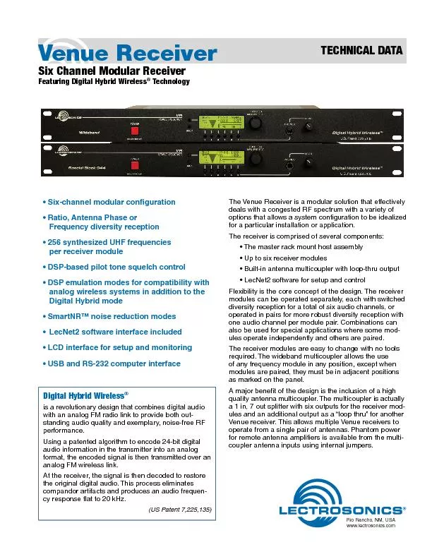
149 Sixchannel modular conguration149 Ratio Antenna Phase or Frequency diversity reception149 256 synthesized UHF frequencies 149 DSPbased pilot tone squelch control149 DSP emulatio ID: 453320

Six-channel modular conguration• Ratio

Share:

Link:

Embed:

Download Presentation from below link

Download Pdf The PPT/PDF document "Venue Receiver Technology TECHNICAL DATA..." is the property of its rightful owner. Permission is granted to download and print the materials on this web site for personal, non-commercial use only, and to display it on your personal computer provided you do not modify the materials and that you retain all copyright notices contained in the materials. By downloading content from our website, you accept the terms of this agreement.


Presentation Transcript

Venue Receiver Technology TECHNICAL DATARio Rancho, NM, USAwww.lectrosonics.com • Six-channel modular conguration• Ratio, Antenna Phase or Frequency diversity reception• 256 synthesized UHF frequencies • DSP-based pilot tone squelch control• DSP emulation modes for compatibility with analog wireless systems in addition to the • SmartNR™ noise reduction modesLecNet2 software interface included• LCD interface for setup and monitoring The front panel provides an easy-to-use LCD interface for setup, and provisions for quick monitoring to assist in troubleshooting. In normal operation, the LCD shows RF and audio levels, diversity status, pilot tone status (where applicable) and transmitter battery status for all six receivers at the same time. Individual screens for each receiver are also available at the touch of a button to provide additional information and setup adjustments.A headphone jack and level control is provided for individual channel monitoring.The rear panel provides six balanced audio outputs on standard XLR connectors, 50 ohm BNC antenna inputs, 50 ohm BNC antenna outputs from the built in zero-gain multicoupler, power jack with a locking connector, USB port and RS-232 serial port for the computer interface. The receiver assembly is powered from an external source at 10 to 18 volts DC through a locking connector, allowing the unit to operate from a wide variety of sources in stage, studio and mobile applications.Two modules are available to further customize the conguration for specic applications. The VRS standard module has xed front-end lters that cover its 25.5 MHz tuning range. The higher selectivity VRT module has tracking front-end lters that retune as the frequency is changed to stay centered over the selected frequency.The modules are a triple conversion, frequency synthesized design, controlled by the microprocessor in the host assembly. A common DSP in the host assembly is used for all six receiver modules to decode the received signals and restore the digital audio. Using a single DSP results in a signicant reduction in cost per channel. The host assembly will handle up to six receiver modules via multi-pin connectors on the side of the main housing. The modules are held in place with snap-in retaining clips. The clips hold the modules rmly but are easy to remove without tools to make needed changes. Every Venue receiver has a built-in multicoupler that utilizes high current RF ampliers and a Wilkinson type splitter for even signal distribution and high isolation between receiver modules. Optimally matched levels allow multiple receivers to be stacked and share a single pair of antennas - a signicant savings in space and cost in multi-channel systems. 10.5-18VDC RS-232 654 LINK 2 321INUSINOUTOUT ANTENNA A LINK 1 LINK 3 1 3 2 1 3 2 1 3 2 ANTENNA B 1 3 2 1 3 2 1 3 2 10.5-18VDC RS-232 654 LINK 2 321INUSINOUTOUT ANTENNA A LINK 1 LINK 3 1 3 2 1 3 2 1 3 2 ANTENNA B 1 3 2 1 3 2 1 3 2 10.5-18VDC RS-232 654 LINK 2 321INUSINOUTOUT ANTENNA A LINK 1 LINK 3 1 3 2 1 3 2 1 3 2 ANTENNA B 1 3 2 1 3 2 1 3 2 The built-in multi-coupler includes “loop through” outputs for stacking multiple Venue receivers.Four versions are available for different applications:Wideband Low (470 - 691 MHz)Special Block 944 (944 - 952 MHz(for licensed broadcasting use)Phantom Power JumpersA remote amplier can be powered directly from the Venue receiver through the coaxial cable. The ALP650 combines a broadband LPDA antenna with an amplier, which is especially useful with the broad bandwidth of the Venue multicoupler. Jumpers are provided on the circuit board to enable and disable the phantom power. The top cover is removed with six screws and the jumpers are set as shown to enable the DC power. VRMJumpers settowards the centerto enable antenna powerDC Power to UFM230DC Power to UFM230 UFM230UFM230 Long coax cabl e Long coax cabl e AntennaAntenna NOTE: The jumpers are set in the OFF position from the factory. The Venue receiver is typically connected to a computer via the USB port. Multiple receivers can be connected to a single computer using a USB hub. The receiver also provides an RS-232 port. 10.5-18VDCRS-232654 LINK 2 321INUSBINOUTOUT ANTENNA A LINK 1 LINK 3 1 3 2 1 3 2 1 3 2 ANTENNA B 1 3 2 1 3 2 1 3 2 10.5-18VDCRS-232654 LINK 2 321INUSBINOUTOUT ANTENNA A LINK 1 LINK 3 1 3 2 1 3 2 1 3 2 ANTENNA B 1 3 2 1 3 2 1 3 2 10.5-18VDCRS-232654 LINK 2 321INUSBINOUTOUT ANTENNA A LINK 1 LINK 3 1 3 2 1 3 2 1 3 2 ANTENNA B 1 3 2 1 3 2 1 3 2USB Hu SmartTuneAn automated scanning process is also available that tunes a receiver module across its tuning range and selects a frequency with the least RF energy. The process takes less than 30 seconds and the screen prompts the operator to turn on a transmitter for the last frequency selected before continuing. Once the transmitter is turned on, the process continues, prompting the operator to continue and select the next receiver to tune. As the receiver is tuned to each frequency, the analysis evaluates RF energy within the channel as well as energy above and below the channel to avoid selecting a frequency adjacent to a high powered signal.The Venue receiver can be used to monitor IFB transmitter signals by switching one or more of the receiver modules to the IFB compatibility mode. Special DSP algorithms emulate the compandor in the IFB system and respond to the pilot tone signal from the transmitter to operate the receiver’s squelch. In this mode, the Venue receiver behaves as though it is a native IFB receiver.The IFB mode is useful for monitoring crew communications and for diagnostics. The spectrum scanning analyzer in the Venue can be used to nd clear frequencies for the IFB system, followed by listening to the IFB transmitter to verify the setup.The pilot tone frequencies in the IFB mode are different than the Digital Hybrid mode to preserve squelch reliability on both systems.Other compatibility modes are also provided for use with analog Lectrosonics transmitters and several models from other manufacturers.front panel LCD interface. Six channel select switches, two selection and navigation switches and a push button rotary encoder control are used with the LCD for setup. The LCD provides a variety of displays, plus an overview display showing transmitter battery status, RF and audio levels, pilot tone status and diversity switching activity for all six receivers. When receivers are paired for ratio or frequency diversity, the two channels are grouped as such in the overview display. Pressing one of the receiver select buttons under the LCD switches to a detail screen for that module. The scanning spectrum analyzer can also be run from the LCD, with manual or automatic location of clear operating frequencies. Scanning can be done with any of the modules to locate clear operating frequencies. A variety of menus are available for all operating parameters. The menu items and adjustments are selected with the rotary encoder knob. Setup and Control with LecNet2 SoftwareLecNet2 is a software interface for the Venue receiver that enables computerized setup, control and monitoring. The software will connect through USB or RS-232 ports on the computer and runs under WindowsVista operating systems.*The main window in the software displays all six receiver modules installed in the assembly at the same time. The display includes frequency information, and audio and RF Levels are displayed real-time. Right click tor Right click the receiver pane to access individual module setup screens and other functions. The Setup Screen for one module allows full conguration of all settings. Multiple Venue receivers can be monitored and controlled at the same time. Popular touch screen control systems can also be congured for remote control and monitoring.Right-clicking anywhere in a Venue Receiver opens a pop up a menu with additional functions available for the associated Venue Receiver, including an RF spectrum scanner and walk test recorder.VRpanel Spectrum Scanner The spectrum scanner provides a visual display of RF activity within the tuning range of the system to quickly locate clear operating frequencies. Frequency and switch settings are displayed for the selected receiver to simplify setup of the associated transmitter.Walk Test RecorderThis convenient feature generates a visual “strip chart” of RF level during a walk test. Audio can be recorded simultaneously on the computer drive as the walk test is conducted. Mentioning transmitter locations during the walk test makes it easy to identify potential problem areas when the recordings are played back. VRpanel Walk Test Recorder*Windows XP and Vista are registered trademarks of Microsoft Corp. DSP-Based Pilot Tonea receiver is turned on without a transmitter signal. In this situation, interference can open the audio output squelch of the receiver and deliver loud noise into the sound system. A pilot tone is a separate signal or tone outside of the receiver. The receiver needs to detect both a valid RF signal and the pilot tone before the squelch will open.There are several ways to implement a pilot tone. One common method is to generate a supersonic audio signal using a crystal. This is helpful, however, the receiver can pick up an invalid pilot tone through multi-signal IM (intermodulation) which can open the squelch.The Digital Hybrid system design uses an ultrasonic pilot tone generated by the DSP to control the receiver squelch, with a different pilot tone frequency for each operating frequency. This eliminates squelch problems in multi-channel systems where a pilot tone signal can appear in the wrong receiver via IM.Brief delays are also employed at turn-on and turn-off to eliminate thumps, pops or other transients that can occur when the power is switched on or off. The DSP generated pilot tone also eliminates fragile crystals which allows the receiver to survive shocks and mishandling much better than older crystal-based pilot tone systems.Diversity ModesThe modular conguration enables several types of diversity reception for various applications. The modules can be used individually for switched diversity reception with each module delivering an audio output, or coupled into pairs for more robust diversity reception where each module pair delivers one audio channel. Front panel Antenna Phase Switching DiversityEffective diversity reception can be implemented by combining the output of two antennas to feed a single receiver and controlling the phase of one antenna. This approach is commonly used for battery powered receivers where available power is limited. RF signal level is monitored continuously, and if the level falls below a certain threshold, the phase of one antenna is switched 180 degrees. If the signal is then stronger, the phase remains switched until the level falls below the threshold again. If the signal is weaker after the switch, the phase is switched back to the previous state and monitoring continues.SmartDiversityThis is a microprocessor controlled algorithm used in the Digital Hybrid system to enhance a phase switching diversity process. The algorithm monitors RF level, rate of change of RF level and audio content to determine the optimal time to switch. The phase switching is more aggressive when the average signal level is weak, and when the signal level falls rapidly compared to the average level. The algorithm also applies “opportunistic switching” to test for the best phase state during the silence of brief pauses in speech.Each receiver module delivers its own audio channel, so the system can provide up to six channels per Venue main assembly. Ratio DiversityThis is an audio combining process that mixes the audio outputs from two adjacent modules in a ratio controlled by comparing the RF signal strengths in the modules. Being a more robust type of diversity, it is normally used for critical applications such as a live broadcast where a dropout could have disastrous results.Two modules are paired and tuned to the same frequency to pick up a single transmitter. The mode is set automatically as either module is switched to this mode. As the RF level in the two receivers is compared, more audio is mixed from the one with the stronger signal in an electronically damped panning process. The panning begins to take place at much higher RF levels than a phase switching technique to anticipate dropouts long before they threaten to produce noise in the audio signal.Module pairs can be selected separately. For example, two modules could be paired for ratio diversity reception of a lead vocalist channel, while the other four modules could be used in the switched diversity mode, each delivering one audio channel.Frequency DiversityThis is an automated redundancy process that pairs two adjacent receiver modules, however, the modules are tuned to different frequencies, each picking up its own matching transmitter. This mode provides robust diversity reception and added protection against battery failure. Common applications include redundant lavaliere microphones for on-air talent in live broadcasts.In this mode the microphones are positioned very close to each other to avoid comb ltering. The outputs of the receivers are mixed together in the same manner as the OptiBlend™ ratio diversity process, with the mix ratio controlled by comparing the RF levels in the modules.Each pair of modules in this mode delivers one audio channel in the same manner as ratio diversity. SmartNRA unique benet of Digital Hybrid Wirelessbased algorithm that address high frequency noise in the audio. With a noise oor at -120 dBV and a frequency audio is more apparent than in conventional wireless systems.The Smart Noise Reduction algorithm works by attenuating only those portions of the audio signal that t a statistical prole for randomness or “electronic hiss.” Because it isn’t simply a sophisticated variable low pass lter as in earlier analog designs, much greater transparency is obtained. Desired high frequency signals having not affected.The algorithm has three modes, selectable from the front panel LCD and the software GUI:OFF - no noise reduction is performed.NORMAL - the factory default setting; enough noise reduction is applied to remove most of the from lavaliere microphones.remove most of the hiss from nearly any signal source of reasonable quality, assuming levels are set correctly at the transmitter.The Venue receiver uses a common microprocessor and DSP for all six receiver modules. This modular design reduces the cost per channel signicantly, and saves rack space by combining a 7-way antenna multicoupler, power distribution and rack mount into a single 1RU assembly for all six channels.Inside the main assembly the encoded radio signals picked up by the receiver modules are sent to the DSP for decoding and restoration of the 24-bit digital audio signals generated in the transmitters.The microprocessor communicates with the operator through the front panel controls, and the USB and serial ports when connected to a computer. It also sends and receives control signals and data from the receiver modules and the DSP.The DSP handles the “number crunching” to restore the digital audio from the encoded signals and communicates pilot tone status to the microprocessor. Once the digital audio is restored, it is nally converted to analog and delivered to the outputs, with control signals from the microprocessor setting the output levels. 581 Laser Road NE • Rio Rancho, NM 87124 USA • www.lectrosonics.com(505) 892-4501 • (800) 821-1121 • fax (505) 892-6243 • sales@lectrosonics.co m 28 October 2010 486.400 - 511.900 hybrid transmitters when they are used together in a Venue system. Receiver Type:Triple conversion superheterodyneVRT Module:11 MHz @ -3 dB�60 dB, 2 uV to 1 Volt VRS:+0 dBm, VRT: +6 dBm Note: Some specications apply only when the receiver is operating in the Digital Hybrid (400 Series) mode. 111.5113.0variable attack and release time constants. The 10 to 18 VDC; 17.2 W max. (1.72 A @ 10 VDC to 1.05 A @ 18 VDC)Weight: VRM with 6 VRT modules: 4.45 lbs. (2018 g) Specications and Features subject to change without notice.