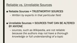
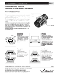
2Grooved Piping System 0601 RIGID SYSTEMSwhich constricts the housing keys into the groove around the full circumference to grip the pipe rigidly This sliding adjustment also forces the key section ID: 98401
Download Pdf The PPT/PDF document "and reliable piping system available. It..." is the property of its rightful owner. Permission is granted to download and print the materials on this web site for personal, non-commercial use only, and to display it on your personal computer provided you do not modify the materials and that you retain all copyright notices contained in the materials. By downloading content from our website, you accept the terms of this agreement.
and reliable piping system available. It is up to three times faster to install than welding, easier and more reliable than threading or flanging, resulting in lowest total installed cost.The system is designed for roll grooved or cut grooved standard pipe or roll grooved light wall pipe. Pipe end preparation is fast and easy either in the shop or on the job site with a variety of Victaulic grooving tools In addition to speed and ease of assembly, the Victaulic system offers varied mechanical benefits to the designer, installer and owner. With the introduction of Zero-Flexrigidity adds to the design versatility. Flexible and rigid couplings can Victaulic also offers the Advanced Groove System (AGS) for 14 Ð 24" (350 Ð 600 mm) sizes. 2Grooved Piping System 06.01 RIGID SYSTEMSwhich constricts the housing keys into the groove around the full circumference to grip the pipe rigidly. This sliding adjustment also forces the key sections into opposed contact on the inside and the outside groove edges, pushing the joint to its maximum pipe end separation (see chart below) during assembly.These rigid couplings provide a rigid joint allowing no expansion/contraction or linear movement. Couplings will push the pipe ends to their maximum allowable separation which must be considered Rigid couplings (Styles 07, W07, 89, 489, 307, HP-70, 741, W741 and others) create a rigid joint, useful for risers, mechanical rooms and other areas where flexibility is not desired. Zero-Flex Style 07 and Style W07 AGS couplings are designed to provide rigidity to permit hanging to ASME B31.1 Power Piping Code and ASME B31.9 Building Services Piping Code. RIGID COUPLING PERFORMANCE Pipe SizeAllowable Inches/mmPipe SizeAllowablePipe End Sep. Inches/mmInches/mmInches/mmInches/mmInches/mm1.0500.055.2500.162026,71,2133,04,111.3150.055.5000.162533,71,2139,74,11.6600.0555.5630.163242,41,2125141,34,11.9000.056.2500.164048,31,2159,04,122.3750.076.5000.165060,31,7165,14,12.8750.0766.6250.166573,01,7150168,34,13.0000.0788.6250.1976,11,7200219,14,833.5000.071010.7500.138088,91,7250273,03,344.5000.161212.7500.13100114,34,1300323,93,34.2500.16108,04,1 Provides rigidity Easy swing-over assembly 4Grooved Piping System 06.01 COUPLING MAXIMUM WORKING PRESSURE Pipe SizeWall Thick. Sched.Coupling Style Ð Working Pressure Ð PSI/kPaAGS RigidFlexibleAGS FlexibleFlexibleFlange Adpt.AGS Flange Flange Adpt.ÐÐ1000ÐÐÐÐÐÐÐÐÐ2026,7ÐÐ6900ÐÐÐÐÐÐÐÐÐ11.315750Ð1000ÐÐ300ÐÐÐÐÐÐ2533,75175Ð6900ÐÐ2065ÐÐÐÐÐÐ750Ð1000ÐÐ300ÐÐÐÐÐÐ3242,45175Ð6900ÐÐ2065ÐÐÐÐÐÐ750Ð1000Ð500300ÐÐÐÐÐÐ4048,35175Ð6900Ð34502065ÐÐÐÐÐÐ22.375750Ð1000Ð500300700300Ð720100025005060,35175Ð6900Ð3450206548252065Ð4965690017235750Ð1000Ð500300700300Ð720100025006573,05175Ð6900Ð3450206548252065Ð4965690017235750Ð1000Ð500ÐÐÐÐÐÐÐ76,15175Ð6900Ð3450ÐÐÐÐÐÐÐ33.500750Ð1000Ð500300700300Ð720100025008088,95175Ð6900Ð3450206548252065Ð4965690017235ÐÐ1000Ð500ÐÐÐÐÐÐÐ90101,6ÐÐ6900Ð3450ÐÐÐÐÐÐÐ44.500750Ð1000Ð500300700300Ð72010002500100114,35175Ð6900Ð3450206548252065Ð4965690017235750Ð1000Ð450ÐÐÐÐÐÐÐ108,05175Ð6900Ð3100ÐÐÐÐÐÐÐÐÐÐÐ450ÐÐÐÐÐÐÐ120127,0ÐÐÐÐ3100ÐÐÐÐÐÐÐ700Ð1000Ð450ÐÐÐÐÐÐÐ133,04825Ð6900Ð3100ÐÐÐÐÐÐÐ700Ð1000Ð450ÐÐÐÐÐÐÐ139,74825Ð6900Ð3100ÐÐÐÐÐÐÐ55.563700Ð1000Ð450300700300Ð720ÐÐ125141,34825Ð6900Ð3100206548252065Ð4965ÐÐ700Ð1000Ð450ÐÐÐÐÐÐÐ159,04825Ð6900Ð3100ÐÐÐÐÐÐÐ700Ð1000Ð450ÐÐ300ÐÐÐÐ165,14825Ð6900Ð3100ÐÐ2065ÐÐÐÐ66.625700Ð1000Ð450300600300Ð72010002000150168,34825Ð6900Ð3100206541352065Ð496569001379088.625600Ð800Ð450300500300Ð7208001500200219,14130Ð5500Ð3100206534502065Ð49655500103501010.750500Ð800ÐÐÐÐ300Ð7208001250250273,03450Ð5500ÐÐÐÐ2065Ð4965550086251212.750400Ð800ÐÐÐÐ300Ð7208001250300323,92750Ð5500ÐÐÐÐ2065Ð4965550086251414.000Ð350300 à350ÐÐÐ300300Ð600Ð350355,6Ð241020652410ÐÐÐ20652065Ð4135Ð1515.000ÐÐ300 àÐÐÐÐÐÐÐÐÐ375381,0ÐÐ2065ÐÐÐÐÐÐÐÐÐ1616.000Ð350300 à350ÐÐÐ300300Ð600Ð400406,4Ð241020652410ÐÐÐ20652065Ð4135Ð1818.000Ð350300 à350ÐÐÐ300300ÐÐÐ450457,0Ð241020652410ÐÐÐ20652065ÐÐÐ2020.000Ð350300 à350ÐÐÐ300300ÐÐÐ500508,0Ð241020652410ÐÐÐ20652065ÐÐÐ2222.000ÐÐ300 àÐÐÐÐÐÐÐÐÐ550559,0ÐÐ2065ÐÐÐÐÐÐÐÐÐ2424.000Ð350250 à350ÐÐÐ300300ÐÐÐ600610,0Ð241017252410ÐÐÐ20652065ÐÐÐ grooved pipe may be doubled. These figures are maximums; for design and installation purposes these figures should be reduced by: 50% for - 3WARNING: Depressurize and drain the piping system before attempting to install, remove, or adjust any Victaulic piping productsThis product shall be manufactured by Victaulic or to Victaulic specifications. All products shall be installed in accordance with current Victaulic installation/assembly instructions. 4Grooved Piping System 06.01 COUPLING MAXIMUM WORKING PRESSURE Pipe SizeCoupling Style à Working Pressure à PSI/kPaWall Thick. Sched.AGS RigidFlexibleAGS FlexibleFlexibleFlange Adpt.AGS Flange Flange Adpt. ÃÃ72049651000690025001723531/2904.000101,640ÃÃÃÃ10006900ÃÃ5003450ÃÃÃÃÃÃÃÃÃÃÃÃÃÃ41004.500114,3407505175ÃÃ10006900ÃÃ5003450300206570048253002065ÃÃ720496510006900250017235108,0 mm4.250108,0407505175ÃÃ10006900ÃÃ4503100ÃÃÃÃÃÃÃÃÃÃÃÃÃÃ41/21205.000127,040ÃÃÃÃÃÃÃÃ4503100ÃÃÃÃÃÃÃÃÃÃÃÃÃÃ133,0 mm5.250133,0407004825ÃÃ10006900ÃÃ4503100ÃÃÃÃÃÃÃÃÃÃÃÃÃÃ139,7 mm5.500139,7407004825ÃÃ10006900ÃÃ4503100ÃÃÃÃÃÃÃÃÃÃÃÃÃÃ51255.563141,3407004825ÃÃ10006900ÃÃ4503100300206570048253002065ÃÃ7204965ÃÃÃÃ159,0 mm6.250159,0407004825ÃÃ10006900ÃÃ4503100ÃÃÃÃÃÃÃÃÃÃÃÃÃÃ165,1 mm6.500165,1407004825ÃÃ10006900ÃÃ4503100ÃÃÃà 3002065ÃÃÃÃÃÃÃÃ61506.625168,3407004825ÃÃ10006900ÃÃ4503100300206560041353002065ÃÃ72049651000690020001379082008.625219,1406004130ÃÃ8005500ÃÃ4503100300206550034503002065ÃÃ720496580055001500103501025010.750273,0405003450ÃÃ8005500ÃÃÃÃÃÃÃÃ3002065ÃÃ72049658005500125086251230012.750323,9304002750ÃÃ8005500ÃÃÃÃÃÃÃÃ3002065ÃÃ72049658005500125086251435014.000355,630ÃÃ3502410300 à 20653502410ÃÃÃÃÃÃ30020653002065ÃÃ6004135ÃÃ1537515.000381,00.375ÃÃÃÃ300 à 2065ÃÃÃÃÃÃÃÃÃÃÃÃÃÃÃÃÃÃ1640016.000406,430ÃÃ3502410300 à 20653502410ÃÃÃÃÃÃ30020653002065ÃÃ6004135ÃÃ1845018.000457,0STDÃÃ3502410300 à 20653502410ÃÃÃÃÃÃ30020653002065ÃÃÃÃÃÃ2050020.000508,020ÃÃ3502410300 à 20653502410ÃÃÃà ÃÃ30020653002065ÃÃÃÃÃÃ2255022.000559,020ÃÃÃÃ300 à 2065ÃÃÃÃÃÃÃÃÃÃÃÃÃÃÃÃÃÃ2460024.000610,020ÃÃ3502410250 à 17253502410ÃÃÃÃÃÃ30020653002065ÃÃÃÃÃà grooved pipe may be doubled. These figures are maximums; for design and installation purposes these figures should be reduced by: 50% for WARNING: Depressurize and drain the piping system before attempting to install, remove, or adjust any Victaulic piping productsVictaulic reserves the right to change product specifications, designs and standard equipment without notice and without incurring obligations. 06.01 Grooved Piping System3 FLEXIBLE SYSTEMS FLEXIBLE COUPLING PERFORMANCEPipe SizeDeÃect. Fr. CPipe SizeDeÃect. Fr. CPipe SizeDeÃect. Fr. CAllow. Pipe End Sep.  Allow. Pipe End Sep.  Allow. Pipe End Sep.   NOTE: These values are based on standard roll grooved pipe. Figures for standard cut grooved pipe may be doubled. See notes on page 4.Minimizesnoise and Provides expansion and Minimizes ContractionExpansionDeflection 2Grooved Piping System 06.01 RIGID SYSTEMS Zero-Flex Style 07 and Transition Style 307 Rigid Couplings have a unique, patented angle pad design which constricts the housing keys into the groove around the full circumference to grip the pipe rigidly. This sliding adjustment also forces the key sections into opposed contact on the inside and the outside groove edges, pushing the joint to its maximum pipe end separation (see chart below) during assembly.These rigid couplings provide a rigid joint allowing no expansion/contraction or linear movement. Couplings will push the pipe ends to their maximum allowable separation which must be considered Rigid couplings (Styles 07, W07, 89, 489, 307, HP-70, 741, W741 and others) create a rigid joint, useful for risers, mechanical rooms and other areas where flexibility is not desired. Zero-Flex Style 07 and Style RIGID COUPLING PERFORMANCE Pipe SizePipe SizeInches/mmInches/mmAllowable Inches/mmInches/mmInches/mmAllowablePipe End Sep. Inches/mmProvides rigidity Easy swing-over assembly R IPS CARBON STEEL PIPE à GROOVED SYSTEM VICTAULIC ¨ IS AN ISO 9001 CERTIFIED COMPANY ¨ REGISTERED TRADEMARK OF VICTAULIC à © COPYRIGHT 2005 VICTAULIC à PRINTED IN U.S.A. à SKU #WCAS-6AYRLR United States Â¥ Phone: 1-800-PICK-VIC (1-800-742-5842) Â¥ Fax: 610-250-8817 Â¥ e-mail: pickvic@victaulic.comCanada Â¥ Phone: 905-884-7444 Â¥ Fax: 905-884-9774 Â¥ e-mail: viccanada@victaulic.com Grooved Piping SystemThe only system that provides the option of rigidity or Ãexibility PRODUCT DESCRIPTION GasketHousingBolt/NutGroove savings from Each joint Proven joint psi (17,235 kPa). . . vacuum For roll or cut grooved pipemm) wall thicknesses Exaggerated for clarity Exaggerated for clarity StandardRoll Grooved Cut Grooved The Victaulic grooved piping system is the most versatile, economical The system is designed for roll grooved or cut grooved standard pipe or roll grooved light wall pipe. Pipe end preparation is fast and easy either In addition to speed and ease of assembly, the Victaulic system offers varied mechanical benefits to the designer, installer and owner. With the ¨ rigid couplings, the option of flexibility or rigidity adds to the design versatility. Flexible and rigid couplings can Victaulic also offers the Advanced Groove System (AGS) for 14 à 24" (350 à 600 mm) sizes.