/
Application Note AP  EN Effective pril  Introduction T Application Note AP  EN Effective pril  Introduction T

Application Note AP EN Effective pril Introduction T - PDF document

liane-varnes
liane-varnes . @liane-varnes
Follow
445 views
Uploaded On 2015-04-19

Application Note AP EN Effective pril Introduction T - PPT Presentation

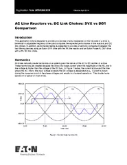
In addition performa nce testing is presented to provide a harmonic comparison between the two filtering devices using an Eaton SVX drive with the 3 line reactor and an Eaton PowerXL DG1 drive with a 5 DC link choke Harmonics All drives naturally cr ID: 52422

addition performa nce

Share:

Link:

Embed:

Download Presentation from below link

Download Pdf The PPT/PDF document "Application Note AP EN Effective pril ..." is the property of its rightful owner. Permission is granted to download and print the materials on this web site for personal, non-commercial use only, and to display it on your personal computer provided you do not modify the materials and that you retain all copyright notices contained in the materials. By downloading content from our website, you accept the terms of this agreement.


Presentation Transcript

Application Note AP04 2003 EN Effective August 2016 AC Line Reactors vs. DC Link Chokes Introduction This application note is designed to provide an overview of why impedance on the line side of a drive is beneficial in variable frequency drives and compares the expected performance of line reactors and DC link chokes. In addition, performance testing is presented to provide a harmonic comparison between the two internal filtering devices using an Eaton SVX drive with the 3% line reactor and an Eaton PowerXL DG1 drive with a 5% DC link choke. Harmonics All drives naturally create harmonics on a system giv en the nature of the AC to DC rectifier of a drive. These harmonics are created because the drive only draws current when the magnitude of the AC, line to line voltage is higher than the voltage of the DC bus. In Figure 1 below , the current is blue and the time where the AC , line to line input voltage exceeds the DC voltage is designated as I d . C urrent is drawn during the crossover point of the phase voltages and results in a humped waveform. This double hump waveform is typical of most drives. Figu re 1: Current draw by drive [1] Application Note AP042003EN AC Line Reactors vs. DC Link Chokes Effective August 2016 2 EATON CORPORATION www.eaton.com Harmonics need to be removed because they can increase the I 2 R losses of the system and they can disrupt the proper functioning of other loads on the system as well as potentially damage them. Additionally, utilities ofte n require customers to adhere to IEEE 519 standards of total harmonic distortion (THD). This specifies the amount of harmonics that can be injected back onto the grid. Harmonics that are generated within in a facility, if not properly filtered, will be s een by the utility. For very small drives, this sinusoidal current draw is not a problem for the utility because the drive is not a significant load on the system. However, for larger horsepower drives additional impedance is normally necessary to remove the impact of these periodic pulses of current. In this regard, the two most common options to choose from for internal filtering are an AC line reactors and a DC link choke. What is a choke and how does it affect harmonics? A choke ( or line reactor) is a coil of wire around a magnetic core that creates a magnetic field when current flows through it. This magnetic field increases the impedance of the line and reduces the total harmonic content injected from the drive onto the facilities electrical syste m. To analyze harmonics, we can examine the harmonic content by breaking down a non - sinusoidal waveform into components. The lower harmonics, like the 5 th and 7 th ,have a larger current magnitude and thus have a larger effect on the total harmonic distortion. This is because f or AC drives with a 3% line reactor or 5% choke, the THD is about 30 - 35% and the magnitude of the harmonic is about 1.5 - 2X the number – i.e. 1/5 = 20% but 5 th may be 30 - 35% alone and with an AC choke, would be closer to 2X. What is an AC line reactor? AC line reactors are added to the input of the drive and placed in series with the incoming line. They help to mitigate harmonics and because t hey are between the line and the drive, they are able to act as a buffer for surges and other transients. The intended purpose of a line reactor is not to offer high levels of surge protection and, if greater protection is desired, a dedicated protective device such as a metal oxide varister (MOV) or a transient voltage surge suppressor ( SPD ) is a much better solution. The disadvantage of an AC line reactor is that they are normally larger than DC chokes and typically more expensive. Figure 2: AC Choke Attached before the Rectifier of a Drive AC Line Reactors vs. DC Link Chokes Application Note AP042003EN Effective August 2016 EATON CORPORATION www.eaton.com 3 What is a DC choke? DC link chokes are connected between the diodes and the DC bus and can be slightly less or slightly more effective at removing harmonics than AC line reactors depending on the order of harmonic being observed. DC link chokes are typically smaller than AC chokes and they add the necessary impedance for harmonic reduction without a drop in voltage. While the DC choke does not add any extra bufferi ng from voltage surges seen by the rectifier , it will protect against current surges. Figure 3: DC Choke Attached to the DC Bus of a Drive Grounding with AC and DC Chokes Grounding with AC Reactor is important in regards to ground fault currents so that they will not flow through the drive and damage it. AC line reactors inherently do this and, while single coil DC chokes do not, newer two - coil DC chokes do provide a ground path , like in the PowerXL DG1 . V oltage D isturbance s with AC and DC Chokes It is also important in t erm s of voltage disturbances to have a choke on the input. S pecifically v oltage sags which are routinely to blame versus over voltage transients for drive failures. Following an undervoltage condition, t he DC bus capacitor must be recharged to match the source voltage level and since voltage can’t instantly change on a capacitor, an immediate inrush of current tries to stabilize the system and capacitor voltages. During a normal startup, the precharge ci rcuit limits this current but following a voltage sag or short interruption, the precharge circuit is not present so the AC line reactor or DC choke must limit the current. Rectifier components are at risk when the power goes back to normal. W ith either an AC line reactor or a DC choke on the input side of the drive , the additional inductance resists the high current inrush protect ing the front end rectifiers and DC bus capacitors in the drive . A 5% DC choke is more effective than a 3% line reactor as it offers much more inductance to limit the current. Application Note AP042003EN AC Line Reactors vs. DC Link Chokes Effective August 2016 4 EATON CORPORATION www.eaton.com Voltage Sag Drive Operating, Drive Trips, Inrush Current into Drive with DC Choke (limits to reasonable level) For short duration overvoltages, such as utility capacitor switching events, the inductance offered by a line reactor or a DC choke limit the inrush (or outrush) of current into the DC bus capacitor protecting the drive. More information on this can be found in the Line Reactors and Line Transients Application Not e (AP04004EN). SVX vs. Power XL DG1 Drive Performance Eaton’s SVX drive offers a standard 3% AC line reactor while the new Power XL DG1 drive comes with a two coil 5% DC choke and MOV surge protection on the line side of the drive. There are two critical aspects to consider when comparing these two solutions: the amount of harmonic reduction and the physical size and layout of the drive. Harmonic Analysis Full load tests were run to examine the amount of harmonic content for both a SVX and a Power XL DG1 drive at 48 0V 30HP. As a point of order, the phase to ground voltage is displayed in the figures below. This is equal to the input voltage divided by root (3). The charts below describe the results. AC Line Reactors vs. DC Link Chokes Application Note AP042003EN Effective August 2016 EATON CORPORATION www.eaton.com 5 Figure 4: SXV - Voltage and Current Input (left); 5 th Harmonic amplitude (right) Figure 5: DG1 - Voltage and Current Input (left); Percent Total Harmonic Distortion (right) Figure 6: Percent Total Harmonic Distortion at Various Harmoni cs for SXV and DG1 0 5 10 15 20 25 30 35 40 THD H5 H7 H11 H13 SVX %THD DG1 %THD Application Note AP042003EN AC Line Reactors vs. DC Link Chokes Effective August 2016 6 EATON CORPORATION www.eaton.com The harmonic analysis indicates that the DG1 with the DC choke exhibits lower %THD at the 3 rd , 5 th , and 7 th harmonics which are the most detrimental to meeting IEEE 519. The DG1 does allow slightly higher %THD of the higher order harmonics which, as was stated before, are more of a concern for EMI sensitive areas. While the DG1 does provide better %THD than the SVX, the DC choke is certainly not a cure all for meeting harmonic requirements for a system. Harmonic systems studies a re the best option for determining the necessar y measures for meeting IEEE 519 as these results may vary with the voltage and power rating of the drives in application. With larger horse power drives, this will typically mean adding a harmonic filter or p hase shifting transformer to the drive to truly meet the IEEE 519 requirements . References [1] S . Islam , “ Characteristic and Non - characteristic Harmonics, Harmonic Cancellations and Relevant I n- ternational Standard in Variable Speed Drives,” Science and Te chnology, 2002 Application Note AP04 2003 EN AC Line Reactors vs. DC Link Chokes Effective August 2016 Additional Help In the US or Canada: please contact the Technical Resource Center at 1 - 877 - ETN - CARE or 1 - 877 - 326 - 2273 option 2, option 6 . All other supporting documentation is located on the Eaton w eb site at www.eaton.com /Drives Eaton 1000 Eaton Boulevard Cleveland, OH 44122 USA Eaton.com © 201 6 Eaton All Rights Reserved Printed in USA Publication No. AP042003EN August 2016 Eaton is a registered trademark of Eaton Corporation. All other trademarks are property of their respective owners