/
Home Power   February  March  Solar Hydrogen Producti Home Power   February  March  Solar Hydrogen Producti

Home Power February March Solar Hydrogen Producti - PDF document

liane-varnes
liane-varnes . @liane-varnes
Follow
403 views
Uploaded On 2015-06-07

Home Power February March Solar Hydrogen Producti - PPT Presentation

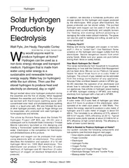
Hydrogen that is made from water using solar energy is a sustainable and renewable home energy supply Make hay or hydrogen while the sun shines Then use the stored hydrogen to produce heat and electricity on demand day or night We got excited about ID: 82119

Hydrogen that made

Share:

Link:

Embed:

Download Presentation from below link

Download Pdf The PPT/PDF document "Home Power February March Solar Hydr..." is the property of its rightful owner. Permission is granted to download and print the materials on this web site for personal, non-commercial use only, and to display it on your personal computer provided you do not modify the materials and that you retain all copyright notices contained in the materials. By downloading content from our website, you accept the terms of this agreement.


Presentation Transcript

Home Power #39 ¥ February / March 1994 Walt Pyle, Jim Healy, Reynaldo Cortezenergy supply. Make hay (or hydrogen)equals 100% efficiency at 20¡C. Typical Home Power #39 ¥ February / March 1994 Electrolyzer?The Hydrogen Wind electrolyzerwas introduced by its designerLawrence Spicer in HP#22 (pp.32Ð34). Hydrogen Wind Inc.electrolyzers are available insingle cell units for small demandor educational use, and in multiplecell configurations which providehigher gas production rates.We purchased a 12 cell 1000 Wattsystem with the gas pressurecontrols and electrical metering.Larger systems with up to 24 cellsor smaller three cell and six cellsystems are available. Anotherarticle by Spicer, describing theindividual cells in more detail alongwith an introduction to cell arrays,appears in HP#26 (pp. 34Ð35).The cell electrodes are fabricatedfrom rectangular metal plates withtabs on one end. Both the anodeand the cathode metal plates aremade from porous, sintered nickel.Two clusters of nickel electrodeplates, 14 for the anode and 14 forthe cathode, are separated byporous plastic sheets foldedaccordion style within a separatorThe plastic separator container is open at the horizontal ends, and closed atthe top and bottom. This lets the larger hydrogen gas bubbles (which escapefrom the negative electrode or cathode) rise in the electrolyte, due to theirbuoyancy, and exit the separator container on one side. The hydrogenwhich evolve from the positive electrode (anode) andexit on the opposite side.The micro-porous polypropylene separator containerand the electrode clusters are housed inside sectionsof steel pipe with flat steel plates welded on one endand bolted on the other end. The steel cell housingshold the water and potassium hydroxide electrolyte,and keep the hydrogen and oxygen gases apart afterthey rise from each end of the separator container.We installed our electrolyzer inside a small weather-protected shelter made from box tubing and sheetmetal. We chose stainless steel sheet metal for itscorrosion resistance to caustic electrolyte and long-lasting Òperma-cultureÓ value. The photograph aboveshows an overview of the system.Solar Power and Utility Grid Backup PowerOur solar electric power is produced by two 16-panelCarrizo Solar ÒMudÓ photovoltaic arrays and a gaggleof other smaller panels. On a good summer day weget up to 75 Amperes at 14 Volts for charging the Above: An overview of the electrolyzer system. The power supplies andelectrical controls are on the far left. Purification equipment is to the right ofthe power controls. The electrolyte reservoir and hydrogen and oxygen floatvalves with pressure gauges are to the right of the purification equipment.Twelve electrolyzer cells are shown on the far right. A feedwater purificationsystem is just below the twelve electrolyzer cells. The caustic electrolytestorage tank is on the ground below the float valves. electric modulesMakeup water purifier Electrolyzer Electric utility grid Oxygen purifierHydrogen purifier Electric power controller Hydrogen gas Hydrogen gas Oxygen gas Electrolyte tank Solar Hydrogen Production Home Power #39 ¥ February / March 1994 house batteries. When the two house battery banks arefully charged, our two 50 Amp SCI charge controllersdisconnect the PV power, and the PV voltage rises. AnEnermaxer controller senses the voltage rise andtransfers the PV power to the electrolyzers to makehydrogen and oxygen during theremainder of the day. A utility gridelectrolyzer power supply is used tomake hydrogen and oxygen whenthere is insufficient solar powerHow Do We Purify the Gases?The gas purification system is shownin more detail in the diagram on right.The hydrogen gas and the oxygen gasare purified by two different systems.BubblersFirst, each gas is scrubbed by passingit through a water bubbler column.Each of the gas scrubbing bubblers ismade from two vertical plastic tubeswith end caps. A pair of fish-aquariumtype bubbler frits was glued into holesdrilled in the inside bottom caps ofeach acrylic plastic tube, usingmethylene chloride solvent. Flow ofgas into or out of a bubbler can thenbe seen by the operator. The bubblersdistilled water using thedrain and fill valves on theWe call these ÒBi-directional BubblersÓ. Thebubblers are tolerant offlow in any direction,without letting the scrub-water into the productstorage system or theelectrolyzer. We got theidea for making thesebubblers from Dr. PeterLehman and hisassociates at HumboldtState University (SchatzSolar Hydrogen and FuelCell Laboratory.)The gases entering thepurifier are saturated withwater vapor and maycontain minute amounts ofcaustic electrolyte aerosoland particulates like rust.After passing through the bubblers the gases are stillsaturated with water vapor, but virtually caustic- andparticulate-free. Installing another coalescer before thebubbler would prevent particulates and some aerosolfrom entering the bubblers. Water Water coalescer Water Water coalescer P Sample acetylene check valveFlashback arrestoracetylene check valveFlashback arrestoroxygen check valveFlashback arrestoroxygen check valveFillDrain Home Power #39 ¥ February / March 1994 Next, the gases are partially dried by passing themthrough coalescing filters. Special materials wererequired for the oxygen coalescer filter to preventspontaneous combustion, and no oil or hydrocarbonscan be present.RecombinersThe hydrogen gas purifier treats the hydrogen gas in acatalytic recombiner. The purpose of the recombiner isto recombine any oxygen impurity in the hydrogenproduct, and make water. The noble metal catalyticrecombiner removes the oxygen impurity to make thehydrogen gas safe to store and handle. As a safetymeasure, we installed flashback arrestors between thefirst and second coalescers and the recombiners. Theflashback arrestors prevent flashback of poor puritygases (oxygen impurity in the hydrogen produced)when they reach the recombiner and ignition source.The recombiners must be installed with their major axisvertical and the entry at the top.Some data recently published by W. Hug et al from theGerman Aerospace Research Establishment(International Journal of Hydrogen Energy, Vol. 18 No.12, pp. 973Ð977) shows that purity of the gasesproduced by an alkaline electrolyzer is affected by thecurrent density and temperature of the cells. From thegraphs we see that the purities of the hydrogen andoxygen gases are poorer at low current densities (suchas when a cloud covers the sun for example). This isbecause diffusion of the gases through the liquidelectrolyte is a more significant fraction of the totalproduction at low current densities.The data also imply that there is more danger of havinghydrogen impurity in the oxygen than the reverse. Notethat the lower flammable limit, 4% for hydrogen impurityin bulk oxygen, is approached at low current densities.How Does One Store the Gases?The hydrogen will be stored in two 0.47 cubic meter(125 gallon) propane tanks, and the oxygen will bestored in one propane tank.REMEMBER: hydrogen gas is safe to store Ñhydrogen/air or hydrogen/oxygen mixtures are NOTsafe to store! Put safety first! Safety is yourresponsibility. It is our intention to give you theinformation you need to follow safe practices.Each of our used propane tanks was cleanedthoroughly and hydrostatically tested to 13.8 bar (20010.3 bar (150 psig.). A pressure switch is installed onthe hydrogen tank feed line to shut off the electrolyzerpower supply when the pressure reaches 6.9 bar (100psig.), the rated maximum output pressure of theThe produced hydrogen gas is pressurized by theelectrolyzer to its maximum rated pressure of 6.9 bar orless. Our two hydrogen tanks hold the equivalent of: 6.9bar x 2 tanks x 0.47 cubic meter = 6.5 cubic meters (atstandard temperature and 6.9 bar pressure).Makeup-water Treatment SystemAs hydrogen and oxygen are produced in theelectrolyzer, water is consumed and it must bereplaced. We produce our makeup-water using thelocal Utility District water, which is piped into the home.We want to prevent the formation of Òmineral scaleÓ onthe surface of the electrodes inside the electrolyzerbecause we want them to last a long time. First, the Amount of Hydrogen in OxygenCurrent Densit y ( mA/cm2 ) (Vol%)0100200300400500600 90°C60°C30°C Taken from measurements by Hug et al, (Vol%)Taken from measurements by Hug et al, 0100200300400500600 lower flammable limit °C Home Power #39 ¥ February / March 1994 water is passed through a 20 micron interference filterto remove particulates like rust and sand. Second, thewater passes through a charcoal drinking water filter toremove organics and chlorine. Third, the water passesthrough a de-ionizing column to remove metallic ions.The results are shown in the table above.As you can see, we removed some scale-formingmaterial. Other elements were below the lowerdetectable level of the instrument (approximately oneppb). Our water before the deionizer and charcoal filteris not very ÒhardÓ at this location; it does not containvery many dissolved minerals. After the de-ionizer thereis a marked reduction in elemental concentrations ofeverything except silicon.Prior to filling the electrolyzer with caustic electrolyte,we conducted a hydrostatic leak test by filling the cellswith purified water and pressurizing the cells andelectrolyte reservoir to 6.9 bar (100 psig) using utilityline pressure. Several tubing fittings leaked untiltightened. Fixing water leaks during the initialhydrostatic test is much better than fixing leaks whenthey involve caustic electrolyte! Getting caustic on yourtools, gloves, safety glasses, and clothes is a real drag.Plan ahead!When installing the tubing clamps, position them so youcan tighten them later when the cells are tied together.An improvement would be to mount the cells higher toallow for access to the clamps from below.Why Do You Need the Caustic Electrolyte?Potassium hydroxide (KOH) in the water makes itelectrically conductive, so that ions can be transportedthrough the electrolyte during electrolysis. See graphshowing the conductivity of the KOH electrolyte as afunction of weight percent KOH in water on right.We have chosen KOH as the caustic. The twelveelectrolysis cells and the electrolyte reservoir holdabout 61 liters (16 gallons) of water plus 15 kilograms(33 pounds) of KOH. This solution is about 23% KOH Water Purification ResultsBeforeAfterElementPurifier, ppmPurifier, ppmbarium0.009nilcalcium7.30.006potassium0.37nilmagnesium0.7nilsodium1.8nilsilicon3.83.8 Concentration % Weight01020304050 Omega Conductivity and pH Measurement Catalogby weight. The strength of the electrolyte solution canbe tested with a battery hydrometer. The specificgravity should be about 1.1.Safety is a Must When Handling Caustic Electrolyte!DANGER!! Potassium hydroxide is very corrosive andhazardous to handle. KOH deserves great respect.Goggles or safety glasses with side protectors, andplastic or rubber gloves are absolutely necessary whenhandling KOH. When caustic comes into contact withthe skin, the natural oils of the skin are chemicallyconverted to a soap, which initially gives a slipperyfeeling. Prolonged contact will dissolve the skin andgive a chemical burn similar but more severe than thatgiven by handling lime or fresh wet concrete with barehands. The best treatment for any accidental spill isflushing with copious amounts of water, orneutralization with a weak acid such as vinegar. Alwayshave a water hose hooked up and operational beforehandling KOH caustic. Keep the electrolyzer outdoorsand locked so only qualified people can service it. Acyclone fence with top and sides might be the solution.DANGER!! The mucous membranes of the eye areespecially susceptible to caustic damage. It has beenestimated that 15 seconds of contact to the eye withconcentrated KOH caustic is enough to producepermanent blindness. If any KOH comes into contactwith the eyes, the best treatment is to flush the eyesimmediately with pure water for at least 15 minutes andseek medical attention. Home Power #39 ¥ February / March 1994 flakes, the water temperature rose from 20¡C (68¡F) toremoved and thread epoxy had to be reapplied. When Home Power #39 ¥ February / March 1994 Inside the Hydrogen Wind gas pressure control systemthere are three float control valves. Two float valves areused for the oxygen and one is used for the hydrogen.When the float valves are filled with gas (vertical acrylictubes with top caps), they float on the electrolyte in thechambers. As each chamber fills with gas theelectrolyte is gradually displaced and the the buoyancyof the float decreases. When the buoyancy is lowenough, the float falls which releases the elastomerplug from the exit passage and allows the gas to leavethe system.The float valves cycle over and over again to releaseÒburstsÓ of gas to the purifiers. You can hear gruntingand wheezing sounds when standing alongside theunit. A little back pressure on the discharge lines makesthe release less violent and quieter. With 1 bar (14.5psig) back pressure we had good results.Budget & Economics for Gas Production & StorageThe approximate cost for the solar hydrogen systemequipment is listed below, broken down by sub-system.The labor used for this installation was our own andwas not tallied. Normally, for a Òfirst timeÓ system suchas this, a rule of thumb is that the labor costs will aboutequal the capital equipment costs. Labor on any futureclone would be significantly less. Capital equipmentcosts could have been reduced by using fewer stainlesssteel and more plastic components.We didnÕt work out the ÒpayoutÓ or ROCE for thissystem before going for it. We made it because wethought it was nifty stuff!It would probably take quite a while to pay for thissystem. However, donÕt forget, itÕs a prototype. Massproduction has a way of cutting costs by factors of ten.How does a cloned system capital cost of $678 sound?Status and Future DirectionStartup of this system occurred during the first week ofDecember 1993. Our next task is to measure the purity EquipmentCost%12 cell electrolyzer system (incl S&H)$2,30034%Photovoltaic modules (used)$1,50022%Gas storage tanks, relief valves, tubing$1,10016%Hydrogen purification system$95014%Oxygen purification system$3505%Caustic storage and transfer$3004%Feedwater purification system$2754%Total