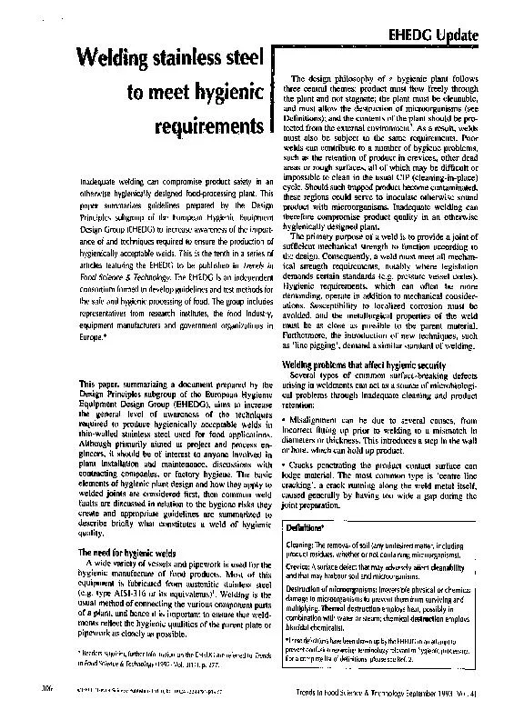
/
to meet hygienic requirements to meet hygienic requirements

to meet hygienic requirements - PDF document

liane-varnes
liane-varnes . @liane-varnes
Follow
416 views
Uploaded On 2016-04-25

to meet hygienic requirements - PPT Presentation

steel welding can compromise product safety in an otherwise hygienically designed foodprocessing plant This paper summarizes guidelines prepared by the Design Principles subgroup of the European Hy ID: 292586

steel welding can compromise product

Share:

Link:

Embed:

Download Presentation from below link

Download Pdf The PPT/PDF document "to meet hygienic requirements" is the property of its rightful owner. Permission is granted to download and print the materials on this web site for personal, non-commercial use only, and to display it on your personal computer provided you do not modify the materials and that you retain all copyright notices contained in the materials. By downloading content from our website, you accept the terms of this agreement.


Presentation Transcript

steel to meet hygienic requirements welding can compromise product safety in an otherwise hygienically designed food-processing plant. This paper summarizes guidelines prepared by the Design Principles subgroup of the European Hygienic Equipment Design Group (EHEDG) to increase awareness of the import- ance of and techniques required to ensure the production of hygienically acceptable welds. This is the tenth in a series of articles featuring the EHEDG to be published in in Food Science & Technology. EHEDG is an independent consortium formed to develop guidelines and test methods for the safe and hygienic processing paper, summarizing a document prepared by the Design Principles subgroup of the European Hygienic Equipment Design Group (EHEDG), aims to increase the general level of awareness of the techniques required to produce hygienically acceptable welds in thin-wallod stainless steel used for food applications. Although primarily aimed at project and process en- gineers, it should be of interest to anyone involved in plant installation and maintenance, discussions with contracting companies, or factory hygiene. The basic elements of hygienic plant need for hygienic welds wide variety of vessels and pipework is used for the hygienic manufacture of food products. Most of this equipment is fabricated from austenitic stainless steel (e.g. type AISI-316 or its equivalents) I. Welding is the usual method of connecting the various component parts of a plant, and hence it is important to ensure that * Readers requiring further information on the EHEDG are referred to in Food Science t~, Technology(1992)Vol. p. Update design philosophy of a hygienic plant follows three central themes: product must flow freely through the plant and not stagnate; the plant must be cleanable, and must allow the destruction of microorganisms (see Definitions); and the contents of the plant should be pro- tected from the external environment 2. As a result, welds must also be subject to the Cleaning: removal of soil (any undesired matter, including product residues, whether or not containing microorganisms). surface defect that may adversely *These definitions have been drawn up by the EHEDG in an attempt to prevent confusion regarding terminology relevant to hygienic processing. For a complete !ist of definitions, pi~ease see Ref. 2. 306 ~lqq ¢. Else~.ier Stiente Pub ist qUK: ,~,'4 --'-~44/qVSO~,.O0 Trends in Food Science & Technology September 1993 IVol. 41 Surface porosity, or excessive inclusions tl become detached thereby creating surface poro trap product and be difficult to clean. • Incorrect penetration of the weld can be ca poor welding technique (e.g. poor control of the current) or incorrect parameters. Ideally, the we should exactly fill the joint and remain flush surface. Underpenetration leaves a crevice at~ (Fig. la), which is a hygienic problem both it and pipework; excessive overpenetration can a up product in pipework, although the excess removed in vessels by grinding. • Lack of full fusion of the weld metal in the joint to the parent metal results in crevice formation at the interface between weld and plate associated mainly with MIG (metal inert gas) weldingl. • Inadequate inert gas shielding (generally nitrogen or argon based) of the reverse surface, when welds are completed from one side only (e.g. pipework welds), results in a roughened weld and heat-affected zone (Fig. lb); this promotes the adhesion of soiling and is difficult to clean. processes appropriate for hygienic fabrications welding processes are in common use, but only a few can deliver welds of hygienic quality free from the types of defects outlined above. The most appropri- ate welding process is the gas tungsten arc welding (GTAW) process, commonly referred to as TIG (tung- sten inert gas) welding (Figs l c, 2). In this process, an arc is struck between a tungsten electrode shrouded with an inert gas and the workpiece. There is often an exter- nal feed of filler wire to the joint, although thin sections (ram) can be joined without filler wire ('autogenous' welds). The filler wire is usually of the same compo- sition as the parent plate, and special consideration is required if mixed metals are involved. In some cases it may be desirable to use a higher-alloy filler wire. The TIG process can be used for pipework and for thin sheet up to -4 mm thick; a manual metal arc pro- cess, followed by post-weld grinding, would more likely be used for thick sections. For many hygienic applica- tions, thin-walled vessels and pipes are commonly used. Automatic (non-manual) versions of TIG welding are now becoming popular and are available for both vessels and pipework. The major advantages of automation are that once the parameters have been established for the geometry and thickness of the joint, high-quality repro- ducible welds are formed, ar,,d that to some extent the operation demands a lower level of skill than hand welding. It is preferable to use the automatic process wherever possible. A surface roughness (R..,) of 3-4 lam can be achieved on high-quality TIG welds, though R.~ values of 7- 8 t.tm are more likely on 'industry standard' welds. This is a little higher than ideal, but is acceptable as the weld area 1 L:,ck of penetration leaves a crevice that can trap product at the inner surface of the weld joint. (b) Roughened weld and heat-affected surface resulting from inadequate inert gas shielding; such a surface promotes the adhesion of soiling and is difficult to clean, tc) Example of a high-quality manual TIG weld. is relatively small overall; however, allowance may be necessary for the additional cleaning times required. The main drawback with TIG welding is the low speed at which the weld runs are accomplished, particularly for thicker-walled vessels. A technique with a faster depo- sition rate, such as MIG or MMA (manual metal arc) can be used on top of a TIG root run adjacent to the product. number of companies specialize in the fabrication of stainless steel plants for the food and pharmaceutical in Food Science & Technology September 1993 IVol. 4 307 holder---- parent metal 2 tungsten arc welding (GTAW), commonly referred to as TIG (tungsten inert gas) welding. Gas shielding is necessary around the tungsten electrode as well as behind the weld, internal to the pipe, to prevent the formation of a roughened surface on the reverse side of the weld (see Fig. 1 b). facilities and experience available in these companies is generally superior to those of sumdard fabricators for the chemical process industry. These com- panies are familiar with the need to protect surfaces during fabrication. In particular, the segregation of stainless steel fabrications from ferrous areas is important, since the use of tools and forming equipment impregnated with ferrous debris can lead to corrosion problems in the finished plant. fabrication of vessels order to achieve good cleanability of a vessel sur- face, it should be smooth; the target value is usually 0.8 pm Ra (Ref. 3). This is achieved in practice by using cold rolled sheet (e.g. type 2B surface finish) 4, typically of --0.3 IJ.m R,, which is available for vessels up to • ,,4mm wall thickness. The sheet should be protected with a vinyl layer. This can be left in place during form- ing and removed on completion of fabrication; a narrow band (-,,50 mm) is usually removed from the proposed weld line to facilitate joining and avoid contamination. The weld area does not generally require any special preparation for thin sheet, but must be free from grease and dirt. "Usually, two runs are applied from opposite sides. The first run will become oxidized on the reverse side, and this must be ground back to sound metal before applying the second run. This must then be ground back flush with the parent plate and polished to restore the surface finish; a final polish at 150 grit size is sufficient to give the required surface roughness. 1. Checklist for hygienic welds in Type AISI-316L austenitic stainless steel pipework pipework and fittings should have an internal surface roughness of 0.8 pm R, maximum. • TIG (tungsten inert gas) welding, also referred to as GTAW (gas tungsten arc welding), must be used as the welding process. Other processes will not give adequate hygienic welds. • Orbital welding machines should be used wherever possible for reproducible high;quality welds. However, manual TIG will be necessan/in some cases. • Welders of proven competence, for example coded for pressure vessel work (BS 5500, ASME VIII, or to appropriate National Pipework Standards) should preferably be used. • The pipe system should be designed such that butt welds are the only construction requiring welding. Pre-assembly of sections in controlled conditions prior to final installation is recommended. The weld must exactly fill the gap between pipe ends/fittings: there should be no underpenetration or excessive overpenetration, and no surface weld defects (e.g. inclusions, porosity, lack of fusion, cracking). • The internal surface must be gas shielded during welding, ideally with an argon purge gas, although nitrogen is acceptable. = Pipe ends must be clean in the fusion zone, and should be cleaned with a stainless steel brush and solvent to remove dirt and grease. • Pipe ends must be cut square with the pipe axis, using mechal~ical means (not by hand), and be free from burrs and distortion. If weld preparations are required (e.g. for wall thicknesses greater than -3 mm), they should not be cut by hand. • Prefabricated fittings if's, elbows, etc.) are required, and these must be consistent with the standard of pipework. • The pipe diameters should be the same; otherwise the smaller must be expanded with a specialized tool, to avoid creating a step and a poor weld. • Misalignment must be limited to of the wall thickness • Trial runs / test pieces are required to establish the optimum conditions for the actual pipe wall thickness used. • Welds may be removed from the installation for inspection if so agreed in advance. thicker-walled vessels, the stainless steel is usually available as hot rolled plate with an R., value of -5 lam, unacceptable for hygienic processing in the as- received condition. Thus, after grinding the internal weld bead flush with the surface, the whole vessel must be polished to the required finish. fabrication of pipework for hygienic welds in stainless steel pipework are summarized in Box I. Orbital welding, an automated version of manual GTAW (TIG), is recommended for the straightforward butt welding (Fig. 3a) of pipework. A good manual can produce welds to the same quality as orbital welding. However, although manual welders may start the day producing excellent-quality welds, their concen- tration may drift as they grow progressively tired and distracted, resulting in the production of substandard welds later during the day. Furthermore, welds are not always in easily accessible or straightfonvard positions Trends in Food Science & Technology September 1993 IVol. 4 orbital welding this may be overcome with the selection of a specific type of weld head, but with a manual welder quality may suffer with the ability of welder to work well at full stretch, in cramped con- ditions, often needing to use mirrors to see the complete weld. An orbital welding machine, once set up cor- rectly, will repeatedly produce welds of the defined quality with no variation. However, orbital welding is extremely sensitive to the setup procedure. Being auto- matic it cannot compensate for any irregularities, for example misalignment or variations in pipe diameter. There should be no time penalty when using orbital welding equipment. In fact, when a machine operator is fully competent, productivity in comparison with manual welding should rise. Top-of-the-range models can be connected to external personal computers, enabling exact measurement of vari- ables (e.g. weld current, pulse setting, speed of travel of weld head and filler wire feed) against set parameters for each weld, and the ability to abort welds in progress if the variables are not maintained within the set limits. of orbital welding welding should be used wherever possible in an installation. Typically it is considered that 80-90% of welds on an installation can be completed with an orbital welder. From isometric drawings of the instal- lation, a degree of preplanning will help maximize the number of welds to be orbitally welded. Those welds difficult to access should, wherever possible, be com- pleted in the workshop prior to installation in the plant. Instances where orbital welding may not be possible are areas of restricted access (the physical size of the weld head may prevent its use in cramped areas) and cases where there is insufficient pipe length to clamp the pipes and weld head together (e.g. pipe bends and T pieces). Prefabricated, extruded Ts and elbows are therefore recommended; typical minimum straight lengths required range from 3 mm to 5 mm depending on the weld head type. diameters The outer diameter of a pipe from a set supplier of a standard can vary by +_10%. In addition, tube manufacturers may produce a wide range of standard sizes that can be quite similar (e.g. metric and imperial sizes). Another complication is the availability of pipework made to various different standards, for ex- ample ISO or ANSI. Where possible, it is important to avoid mixing different pipe standards; otherwise mis- alignments can occur. If the diameters of two pipes to be joined are not the same, then the smaller pipe should be expanded to match the larger. Specialized hydraulic expanding tools are available for this purpose, ensuring the pipe remains cylindrical. cutting and surface preparation A mechanical mill or saw should be used to en- sure the cut face is exactly at right angles to the (b) wrong 0.25mm misalignment 20% wall thickness Fig. 3 is the key to obtaining a good-quality weld (a). Pipe ends should be cut at right angles and care should be taken to avoid removing the corner edges (b). Pipes to be joined should be flush and should be of the same wall thickness and diameter to avoid misalignment (c). Trends in Food Science & Technology September 1993 Vol. 4 309 axis of the pipe. Any burrs must be removed with either a file or emery paper. Care must be taken to avoid removing the comer edges of the pipe (Fig. 3b), as this can cause problems with fusion of the root of the weld. The pipe surface 25 mm either side of the weld should ~ghened up wi~ a stainless steel wire brush or emery paper, then ~th the pipe ends and the roughened surface ~a should be de~ed with a solvent, Failure to do so leads to porosi~ in the weld; as any organic substances remaining on the metal surface me vaporized during the welding process and form bubbles in the weld metal. alignment Alignment and clamping tools are available to ensure accurate alignment. However, this accuracy should be checked periodically with the wear of the instrument. Misalignment must be limited to of the maximum wall thickness. There should ideally be no gap between pipe faces, but mm is acceptable (Fig. 3c). treatments contact weld surfaces fall into two categories: those which are accessible (e.g. vessels), and those which, once completed, remain inaccessible during their service life. Accessible welds are often ground and pol- ished as described earlier; inaccessible welds should be completed such that further treatment is not required. The next stage in either case is to wash the internal surfaces, once any protective film has been removed. Washing may consist of several stages. A degreasing treatment may be applied to ~emove grease and oily residues. In general, all surfaces should be cleaned by washing with an alkaline detergent solution, followed by rinsing with water of good microbiological quality, usually cholorinated water to 2 ppm available chlorine maximum. After draining, the access points should be covered and sealed, in some circumstances there is an additional requirement to passivate the weld area on the product contact side. This is normally achieved by the use of, for example, nitric acid solutions, increasing the corrosion resistance of the weld area. The external welds may also need treating. Where excel- lent cleanability of the external surface is demanded, weld beads should be ground smooth and polished. It may be undesirable to grind autogenous welds since this can lead to thinning in the weld area and consequently to mechan- ical or safety issues. However, where external cleaning is less important it may simply be possible to remove the 'heat colours' from the weld area with a proprietary 'pick- ling paste', followed by cleaning; the treatment used will depend upon the external cleaning requirements. assurance and inspection for hygienic welds hygienic weld should be produced using a quality approach, since in many cases final inspcction can be difficult or impossible (e.g. in pipes). The general approach is first to prepare a specification of the requirements, including the defect acceptance cri- teria and surface finish. Essentially there should be no surface-breaking defects as outlined in the section on problems in welding; these requirements may be in addition to more stringent requig:ments such as relevant pressure vessel codes. The method of inspection and repair procedures also needs to be agreed at the out~,et. Prospective fabricators can be audited for their fit- ness to manufacture by considering ,.he general approach and layout of the workshop, and the qualifications of the welders. Representative samples of workmanship should be requested, examined, and if acceptable used as a reference for the standard required' in the plant. Few techniques are suitable for the inspection of stainless steel equipment. Great reliance is placed on visual inspection of weld seams in vessels, aided by dye penetrant tests for highlighting surface defects. The sur- face finish of polished weld seams can be measured using portable equipment such as the Surtronic 10 surface roughness indicator (Rank Taylor Hobson, Leicester, UK). Pipework is more restricted, with visual inspection by fibre optic devices inserted down the pipe the only realistic option. Of course, sample welds can be cut out for destructive assessment; if this course is fol- lowed, it must be by prior agreement in the specifi- cation, and the action level should have been agreed. For example, the right to remove 2% of welds may be requested, and the welds remade if the work is found to be substandard by comparison with the agreed test samples. For critical applications, a more rigorous approach is required. Each weld must be identified with a unique ref- erence, and for convenience grouped into segments. This can be achieved simply in pipework systems by grouping together all welds using the same gas purge. If there are failures in the group, then 100% of the welds for that segment should be examined. External inspections of all welds should be carried out. A documented record indi- cating the identity of the welder, inspection details and outcome, together with weld variables may be required. authors gratefully acknowledge the contributions of members of the 3-A Steering Committee, resulting from cooperation between this organization and the EHEDG. This paper summarizes guidelines recommended by the European Hygienic Equipment Design Group (EHEDG) subgroup on Design Principles, and has been approved by the EHEDG. The full report, by C.A. Eastwood, D.L. Woodall, D.A. Timperley, G.J. Curiel, P. Peschel and G. Hauser, is available from: D.A. Timperley, Campden Food and Drink Research Association (CFDRA), Chipping Campden, UK GL55 6LD (tel. +44-386-840319; fax: +44-386-841306). AISI Steel Products Manual, Stainless and Heat Resisting Steels pp. 18-19, American Iron and Steel Institute, Washington, DC, USA Hygienic Equipment Design Criteria in Food Sci. Technol. 225-229 Surface Roughness- Parameters, their Values and General Rules for Specifying Requirements (IS() 468:1982)(1982) Standards Organization Specification for Stainless and Heat Resisting Steel Plate, Sheet and Strip (BS 1449:Pa.,t 2:!983)(1983) Standards Institution 310 Trends in Food Science & Technology September 1993 Vol. 4