/
Application Note AN JTAG Testing of IDTs Multichip Modules Introduction IDT currently Application Note AN JTAG Testing of IDTs Multichip Modules Introduction IDT currently

Application Note AN JTAG Testing of IDTs Multichip Modules Introduction IDT currently - PDF document

lindy-dunigan
lindy-dunigan . @lindy-dunigan
Follow
527 views
Uploaded On 2014-12-24

Application Note AN JTAG Testing of IDTs Multichip Modules Introduction IDT currently - PPT Presentation

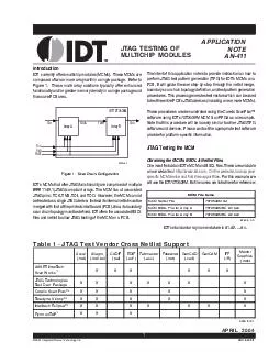
These MCMs are composed of two or more arrays within a single package Refer to Figure 1 These multiarray solutions typically offer enhanced functionality andor greater memory density in a single package and thus save PCB area Figure 1 Scan Chain Con ID: 29044

These MCMs are composed

Share:

Link:

Embed:

Download Presentation from below link

Download Pdf The PPT/PDF document "Application Note AN JTAG Testing of IDTs..." is the property of its rightful owner. Permission is granted to download and print the materials on this web site for personal, non-commercial use only, and to display it on your personal computer provided you do not modify the materials and that you retain all copyright notices contained in the materials. By downloading content from our website, you accept the terms of this agreement.


Presentation Transcript

1 JTAG Testing of IDT’s Multichip ModulesIDT currently offers multichip modules (MCMs). These MCMs arecomposed of two or more arrays within a single package. Refer toFigure 1. These multi-array solutions typically offer enhancedFigure 1. Scan Chain ConfigurationMCMs that offer JTAG functionality are comprised of multipleIEEE 1149.1 (JTAG) compliant arrays. The MCM has all associatedJTAG pins: TCK, TMS, TDI, and TDO. However, the MCM cannotbe treated as a single JTAG device. Instead its internal netlist must bemerged with that of the printed circuit board (PCB). Also, its boundaryfiles and netlist to allow JTAG testing of the MCM on a PCB.perform JTAG test pattern generation (TPG) for IDT’s MCMs on aPCB. It will guide the user step-by-step through the netlist merge,procedures. This process generates test vectors which can be usedto test the entire PCB’s JTAG devices (including one or more MCMs).software using IDT’s 70T3539M MCM & an FPGA as an example.Note that this procedure will be loosely similar to other JTAG TPGsoftware and devices. Please contact the appropriate test softwareJTAG Testing the MCMat http://www.idt.com. On the website, look up yourwill use the IDT70T3539M. Its file names are listed here for reference: MCM File NameMCM Netlist File70T3539M.netMCM BSDL File for Array A70T3539MBC_A1.bsdMCM BSDL File for Array B70T3539MBC_A2.bsd6483 tbl 00 3 JTAG Testing of IDT’s Multichip Modulestransparent components such as resistors, switches, etc. Thesedevices can be tested “through” without affecting test results.modifications. Thus, we will not use these files.Procedure for Generating Interconnect Test Vectors1.First start the ScanPlus™ TPG software.A screen-shotis shown below.2.Select the “Interconnect” button in the “Test Step Types”3.To select the netlist file, click on the first row “Netlist File:”where the input files are located. Select the “MyPCB”4.To select the topology file, from the ScanPlus TPG mainscreen, click on the “Topology File:” row. Click the “Add” 5.Note that this example does not require a Constraint file. Ifrow. Click the “Add” command button. Select your6.Note that this example does not require a Netlist Edit file.However, you may choose to add a Netlist Edit file byselecting the fourth row in the main screen. Click the “Add”command button. Select your netlist edit file (.edt) and click7.Note that this example does not require a Merge Pin LibraryPin Library” from the main window. Click on the “Add”command button. Select your merge library file (.lib) and8.Save this test step by clicking on the toolbar disk icon, orselect “Save Test Step” from the “File” menu. This test will“MyPCB Interconnect” test file (.tst) for this example.9.Click on the “Generate” command button. The softwarevectors. While running the main screen will display anyWarning or Error messages. Once completed, the softwarecreates a .cvf file. This file may be used with ScanPlusRunner™ for testing the PCB’s interconnections. 4 JTAG Testing of IDT’s Multichip Modules Telesis Netlist Fileare many different netlist file formats, but ScanPlusTPG uses the Telesis( or standard Allegro) file format because of its simplicity.of a Telesis netlist file is shown in Table 3. The first keyword is “$PACK-and finally the device ID. Some versions of Telesis omit the packageblock and ignores it completely. After all package definitions have beenAn example of a Telesis netlist is shown in Table 3. Note that this is notTable 3 - Telesis Netlist Structure The IDT logo is a registered trademark of Integrated Device Technology, Inc. $PACKAGES {package type}! {package subtype/value}; {device ID} {package type}! {package subtype/value}; {device ID}...$ENDCORPORATE HEADQUARTERSfor SALES:for Tech Support:6024 Silver Creek Valley Road800-345-7015 or 408-284-8200408-284-279495138fax: 408-284-2775www.idt.com