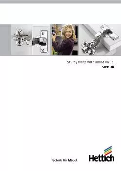
/
Sturdy hinge with added value. Sturdy hinge with added value.

Sturdy hinge with added value. - PDF document

lindy-dunigan
lindy-dunigan . @lindy-dunigan
Follow
411 views
Uploaded On 2015-08-07

Sturdy hinge with added value. - PPT Presentation

2 easy to use great performance 3 Easy installation and convenience in the standard segment SlideOn from Hettich Choosing the SlideOn concealed hinge you benefit from the high level of quality you ID: 102083

2 easy use great performance 3 Easy

Share:

Link:

Embed:

Download Presentation from below link

Download Pdf The PPT/PDF document "Sturdy hinge with added value." is the property of its rightful owner. Permission is granted to download and print the materials on this web site for personal, non-commercial use only, and to display it on your personal computer provided you do not modify the materials and that you retain all copyright notices contained in the materials. By downloading content from our website, you accept the terms of this agreement.


Presentation Transcript

Sturdy hinge with added value. 2 easy to use, great performance 3 Easy installation and convenience in the standard segment: SlideOn from Hettich. Choosing the SlideOn concealed hinge, you benefit from the high level of quality you are used to from an all-steel fitting.With its position-retaining feature, SlideOn reliably opens and closes the door in any situation. A spring moves the door all the way open or all the way closed, securely holding it in either posi-tion. The position-retaining function additionally comes with a practical benefit as it prevents scratches on the inner surface of a door from fittings moving inside. 4 Hettich and the environment: committed to responsible practice, active protection, innovative thinking.Hettich takes a responsibility for the world we live in. This aware-ness defines the strict policy of environmental management we practise. Our environmental officer has taken personal responsi-bility for these aspects throughout the company group over a period of many years. In addition, a separate environment committee has been established for each production site. We regard statutory provisions as minimum requirements. At significant sites we also implement the stringent EMAS Directive. And we drive forward developments that in future will help to save even more raw materials and support the necessary endeavours towards sustainability.Hettich standard for product materialsHettich underpins its commitment by applying an internal standard for product materials. This ensures that every product – from production to disposal – satisfies all environmental requirements. Products from Hettich come with a long life. Appropriately foresighted, our rigorous standards are formulated to ensure that international legislation is met as well. This provides a reliable basis for marketing furniture world-wide.Hettich environmental managementHettich started introducing effective environmental manage-ment systems under the stringent EMAS Regulation (currently: EC Regulation No. 761/2001, including EN ISO 14.001/2004) as long ago as 1996. This not only enables us to improve our environmental performance on a broad front but also achieve a high level of safety which, not least, also benefits our customers. This is why we also require our suppliers to meet the necessary minimum standards of environmental protection, industrial safety, health care and social welfare.The results achieved in the drawer-runner and drawer-system product segment at the Kirchlengern operation illustrate the impressive effects these measures have and verifiably demon-strate our tireless endeavours to translate words into action:Relief to the environment between 1997 and 2008:Specific water consumption: 56 per centSpecific power consumption:21 per centSpecific heat consumption: 84 per centSpecific CO emissions: 29 per cent 5 Ü berdehntest F Vertikaltest FG Verschleißtest G F G Zuschlagtest The SlideOn hinges are constantly monitored for quality.The varying quality standards demanded by different markets and segments are each taken into account. The diagrams below show examples of some of the testing processes and what they Life cycle testThe door must withstand a defined number of opening and closing cycles with a defined additional load G. Closing testThe door is opened by 30° with a defined additional load of G and pushed closed from this position by means of the falling weight. Horizontal testIn this test, also referred to as the overstraining test, the door is over-opened with a defined test force F.Vertical testThis is where the door is subjected to specific number of opening and closing cycles under a defined additional load G. Slide-on hingeSlideOnTechnical informationReveal F2 x minimum revealMounting options:There are three basic mounting options.Minimum door reveal:The minimum reveal, also known as door clearance or minimum clearance, is the space required at the side for opening a door.The amount of door clearance depends on cup distance C, door thickness and the type of hinge selected. Radii on the door edges reduce the minimum clearance.The required minimum reveal is shown in the table for the respective hinge types.For half-overlay applications, the total reveal selected between the doors must be at least twice the door clearance. Both doors can then be opened at the same time.This is where the door is positioned inside the cabinet, i.e. next to the cabinet side panel. Here too, a gap is needed so that the door can open reliably. Highly cranked hinges are used here.Half overlay:This is where two doors are positioned in front of a cabinet centre panel, with the required overall reveal between them.In other words, each door has a reduced overlay. Cranked hinges are used.Full overlay: This is where the door is positioned in front of the cabinet side panel, with only a small gap remaining at the side to provide the space necessary for the door to open reliably. Overlay AReveal FDoor width up to 600 mm up to 900 up to 1600 up to 2000 up to 2400 Door heightNumber of hinges per door:Door width, height and weight as well as the material quality of the door are decisive factors in determining the number of hinges required. The factors encountered in practice differ widely from case to case. For this reason, the number of hinges specified in the diagram must be understood as a guide only. If in doubt, it is recommended to carry out a trial door For reasons of stability, the distance between the hinges must always be made as large as possible. X = hinge spacing(Guide values for 19 mm chipboard panels in a density of 750 kg/mCup distance C:Cup distance C is the distance between door edge and the edge of the cup drilling. Resulting from the type of door movement, the maximum cup distance depends on the specific hinge type. The greater the distance selected for cup distance C, the smaller door clearance will be, i.e. the minimum reveal required.Door overlay:Door overlay, or overlay A, is the distance by which the door extends beyond the cabinet side.Reveal F:The reveal is the distance from the outer edge of the door to the outer side of the cabinet in the case of full overlay appli-cations, and the distance between two doors in the case of half-overlay applica-tions. With the inset door, the reveal is the distance from the outer edge of the door to the inside of the cabinet side panel. 1. 7 Distance DMounting plates are available in various thicknesses, with their effective height being identified by the distance value.The starting point for calculating the required distance is the chosen mounting option with defined door overlay or reveal.Proceeding from cup distance and door thickness, the first step is to determine the necessary minimum reveal from the table. If this is too large for the chosen overlay, the minimum reveal can be reduced by increasing cup distance C as well as by rounding the door edges. The distance required for the mounting plate is now determined using the formula relating to hinge cranking. Half-overlay application with a total reveal of 5 mm between the doors.Hinge 2333, 9.5 crankingSide panel thickness 16 mm, door thickness 22 mm, ideal cup distance 3 mm Value given in the table for minimum reveal: 3.1 mm, i.e. total reveal should be at least 6.2 mm. Yet to obtain a total reveal of 5 mm, cup distance is increased to 4.0 mm. The table now shows a minimum reveal of 2.8 mm, providing a total reveal of 5.6 mm. The door edges are additionally provided with a radius of 1.0 mm, once again reducing the minimum reveal shown in the table from 2.8 mm to 2.4 mm and, with this, the total reveal from 5.6 mm to 4.8 mm. Consequently, a reveal of 5 mm is now possible between the doors.Door overlay A = (side panel thickness - reveal) /2 doors = (16.0 mm - 5.0 mm) / 2 = 5.5 mmThe formula for calculating distance for a 9.5 mm cranked hinge produces: Distance D = cup distance C + 5.0 mm - overlay A = 4.0 mm + 5.0 mm - 5.5 mm = 3.5 mmIf the distance calculated is not available (see page 10/11),the next smaller distance is selected.So, in this example, a distance of 3.0 mm is selected and the hinge is moved across 0.5 mm by means of a side adjustment screw.Installing SlideOnSlide slot (1) at the end of the hinge side section under screw (A) pre-mounted on the mounted plate and push in direction of arrow.The screw is now tightened when the door is positioned at the required depth.Make sure that overlay adjustment screw (B) is pushed under slot (2) in the mounting plate.By way of illustrationscrew (B)screw (A)Slot (1)Slot (2)View from belowCross-sectional viewAdjustment screw (B) from below2.5 mm0.5 mm2.0 mm2 mmDoor adjustmentsHeight adjustmentOverlay adjustmentNeedless to say, SlideOn hinges provide three-dimensional adjustability for exact positioning of door height, side and depth.Depth adjustmentSlightly loosen mounting-plate fixing screws and align door height. Now retighten fixing screws.Loosen fixing screw and adjust the gap between door and side of cabinet. Now retighten fixing screw.Turn screw Door overlay is (-).Turn screw Door overlay is (+). 95° 1111,8 øC5,5ø1052 BBT4 48ø 35C6 ??? BBT4 ???? ø5 9,545 BBT4 ???? ø5 Cup diametre 35 mmCup distance C up to 6 mmCup depth 11.1 mmWith self-closing featureOverlay adjustment: +0.5 mm / -2.5 mm+2.0 mm / -2.0 mm depth adjustmentSlide-on hingeSlideOn 2333Opening angle 95° Cup installationFull overlay 0 mmHalf overlay9.5 mm 16 mmT 421 078 6601 078 6611 078 662T 42/24(Wood-screws1 080 8341 080 8351 080 836T 42/35(Turbo fixing screws9 010 9099 010 9129 010 913T 431 078 6631 078 6641 078 665T 42/481 084 9271 084 9321 084 937T 42/54(Turbo fixing screws9 038 3969 038 3989 038 399T 42/109 037 0349 037 3499 037 351 BTH Door protrusion (T), hinge protrusion (B) and installed hinge depth (H): Hinge cranking (mm) K 0 mm9.5 mmK 16 mm (full overlay(half overlay) Measurements refer to a mounting plate with 1.5 mm distance and 3 mm cup distance. If distance changes, the and "B" dimensions increase accordingly.Installed depth measured from inside door face Cup distance Door thickness mmC mm 21The minimum reveal is reduced for doors with rounded edges:Radius 1 mm: Values shown in table - 0.4 mmRadius 3 mm: Values shown in table - 1.2 mmMinimum reveal (F) to allow per door (door clearance):For determining cup distance and mounting-plate distanceOverlay AReveal FCalculating required mounting-plate distance (D):In relation to chosen door overlay (A) and cup distance (C)(0 mm hinge cranking)Half overlay(9.5 mm hinge cranking)6 mm hinge cranking)For Technical Information, see pages 6 to 7; for mounting plate, see pages 10 to 11* 0 mm hinge cranking cannot be combined with a 0 mm distance mounting plateDistance DOverlay AReveal F Cup distance CDistance DDistance DOverlay A2 x reveal FCup distance CDistance DReveal FCup distance CDistance D =Cup distance C - 1.5 mm + reveal F Distance D =Cup distance C + 5.0 mm - overlay A Distance D* =Cup distance C + 14.5 mm - overlay A 10 37 32 ø 37 32 37 32 ø 12 MPL 2006 KMounting plates system 2006 K Hole line mmTotalOrder no.Screw-on cross mounting platewith oblong holes, hole distance ø 4.0 mm; hole diametre 32 mm For attachment with countersunk wood-screws, ø 4.5 x 16 mm min.Height adjustment: ± 2 mm Steel, nickel-plated*) do not use for 2333 CO1 079 197*1 079 1981 079 19911.51 079 200Screw-on cross mounting platewith oblong holes and pre-mounted direct fixing screws 32 mm hole spacing For attachment with pre-mounted direct fixing screwsHole diametre: ø 5 x 12 mmHeight adjustment: ± 2 mm Steel, nickel-plated1 079 221*1 079 2221 079 22311.51 079 224*) do not use for 2333 COScrew-on cross mounting platewith oblong holes; hole distance 32 mm For attachment with locating pins andasymmetrically pre-mountedHole diametre: ø 5 mm x 7.5 mmHeight adjustment: ± 2 mm Steel, nickel-plated1 079 2101 079 21111.51 079 212 ColourOrder no.Cover cap 11 min15 ø 37 37 ø min.15 The Hettich-Direkt mounting plate is the ideal attachment system for centre panels in thick-nesses of 15 mm and over.Provided with pre-mounted locating pins, the mounting plate is simply pushed into the 5 mm ø hole line, seating it firmly in the hole even before it is screwed into place.This significantly simplifies attachment to the centre panel as well as to the cabinet side.Also pre-mounted in the mounting plate, the special screws are asymmetrically positioned, preventing them from meeting when fitted to the centre panel.This patented solution also permits the use of longer screws in half-overlay applications. The high tear-out strength this achieves provides safety in everyday use.The oblong holes retain full height adjustability! 1103-046-SlideOn-0511-HMV/ENGund Vertriebs GmbH & Co. KGVahrenkampstrasse 12-16www.hettich.com