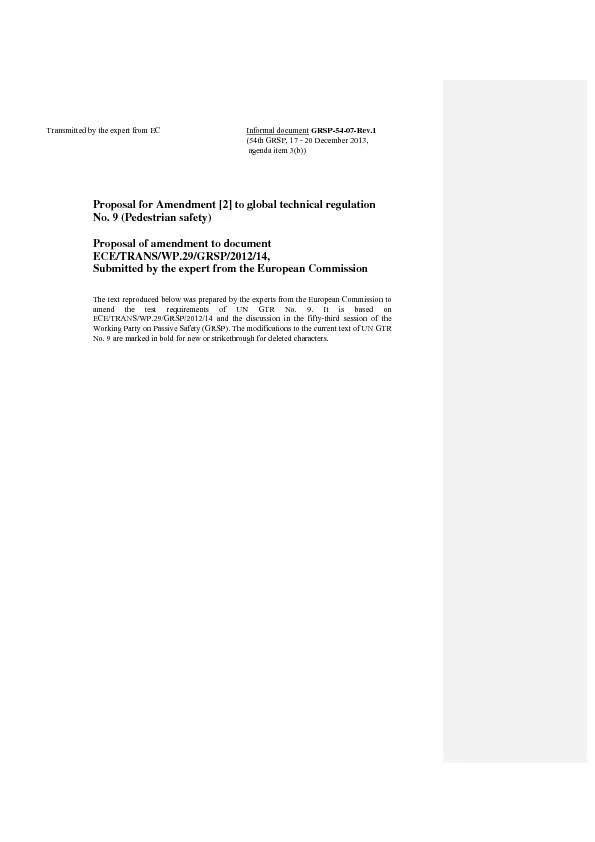
/
Transmitted by the expert from EC Informal document GRSP-54-07-Rev.1 Transmitted by the expert from EC Informal document GRSP-54-07-Rev.1

Transmitted by the expert from EC Informal document GRSP-54-07-Rev.1 - PDF document

lindy-dunigan
lindy-dunigan . @lindy-dunigan
Follow
399 views
Uploaded On 2016-08-11

Transmitted by the expert from EC Informal document GRSP-54-07-Rev.1 - PPT Presentation

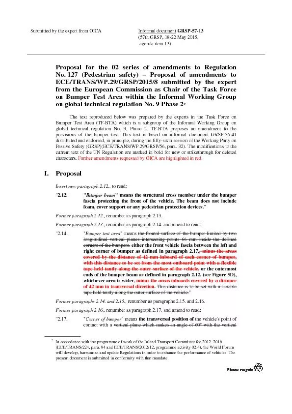
54th GRSP 17 20 December 2013 agenda item 3b Proposal for Amendment 2 to global technical regulation No 9 Pedestrian safety Proposal of amendment to document ECETRANSWP29GRSP2 ID: 442705

(54th GRSP

Share:

Link:

Embed:

Download Presentation from below link

Download Pdf The PPT/PDF document "Transmitted by the expert from EC Inform..." is the property of its rightful owner. Permission is granted to download and print the materials on this web site for personal, non-commercial use only, and to display it on your personal computer provided you do not modify the materials and that you retain all copyright notices contained in the materials. By downloading content from our website, you accept the terms of this agreement.


Presentation Transcript

Transmitted by the expert from EC Informal document GRSP-54-07-Rev.1 (54th GRSP, 17 - 20 December 2013, agenda item 3(b)) Proposal for Amendment [2] to global technical regulation No. 9 (Pedestrian safety) Proposal of amendment to document ECE/TRANS/WP.29/GRSP/2012/14, Submitted by the expert from the European CommissionThe text reproduced below was prepared by the experts from the European Commission to amend the test requirements of UN GTR No. 9. It is based on ECE/TRANS/WP.29/GRSP/2012/14 and the discussion in the fifty-third session of the Working Party on Passive Safety (GRSP). The modifications to the current text of UN GTR No. 9 are marked in bold for new or strikethrough for deleted characters. ECE/TRANS/WP.29/GRSP/2012/14 I. Proposal In the text of the regulation (part B), Paragraph 2.1., the reference to footnote 2 and footnote 2, correct as footnote 1Paragraph 3.1., amend to read: "3.1. "Adult headform test area" is an area on the outer surfaces of the front structure. The area is bounded, in the front, by a wrap around distance (WAD) of 1,700 mm and, at the rear, by the rear reference line for adult headform and, at each side, by the side reference line. (a) in the front, by a wrap around distance (WAD) of 1,700 or a line 82.5 mm rearward of the bonnet leading edge reference line, whichever is most rearward at a given lateral position, (b) at the rear, by a WAD 2,100 or a line 82.5 mm forward of the bonnet rear reference line, whichever is most forward at a given lateral position, and (c) at each side, by a line 82.5 mm inside the side reference line. The distance of 82.5 mm is to be set with a flexible tape held tautly along the outer surface of the vehicle.Insert a new paragraph 3.8., to read: 3.8. "Bonnet top test area" is composed of the child headform test area and the adult headform test area as defined in paras. 3.13. and 3.1. Paragraphs 3.8. and 3.9. (former), renumber as paragraphs 3.9. and 3.10.Paragraph 3.10. (former), renumber as paragraph 3.11. and amend to read: "3.11. "Bumper test area" means the frontal surface of the bumper limited by two longitudinal vertical planes intersecting the corners of the bumper and moved 66 mm parallel and inboard of the corners of the bumpers points 66 mm inside the defined corners of the bumper. This distance is to be set with a flexible tape held tautly along the outer surface of the vehicle." Paragraph 3.11. (former), renumber as paragraph 3.12. Paragraph 3.12. (former), renumber as paragraph 3.13. and amend to read: Child headform test area" is an area on the outer surfaces of the front structure. The area is bounded, in the front, by the front reference line for child headform, and, at the rear, by the WAD1700 line, and by the side reference lines. (a) in the front, by a WAD 1,000 or a line 82.5 mm rearward of the bonnet leading edge reference line, whichever is most rearward at a given lateral position, (b) at the rear, by a WAD 1,700 or a line 82.5 mm forward of the bonnet rear reference line, whichever is most forward at a given lateral position, and (c) at each side, by a line 82.5 mm inside the side reference line. ECE/TRANS/WP.29/GRSP/2012/14 The distance of 82.5 mm is to be set with a flexible tape held tautly along the outer surface of the vehicle.Paragraphs 3.13. to 3.18. (former), renumber as paragraphs 3.14. to 3.19. Paragraph 3.19. (former), shall be deleted Insert new paragraphs 3.20. to 3.20.2., to read: 3.20. "Measuring point" The measuring point is may also be referred to as "test point" or " impact point". In all cases, the result of the test shall be attributed to this point, independent of where first contact occurs. 3.20.1. "Measuring point" for the headform test means a point on the vehicle’s outer surface selected for assessment. The measuring point is where the headform’s profile contacts the vehicle’s outer surface cross section in a vertical longitudinal plane through the center of gravity of the headform (see Figure 6A). 3.20.2. "Measuring point" for the lower legform to bumper test and the upper legform to bumper test is located in the vertical longitudinal plane through the central axis of the impactor (see Figure 6B). Paragraphs 3.20. to 3.24. (former), renumber as paragraphs 3.21. to 3.25. Paragraph 3.25. (former), shall be deleted. Figure 6, shall be deleted Insert new Figures 6A and 6B"Figure 6A Measuring point in the vertical longitudinal plane through the center of the headform impactor (see paragraph 3.20.1.) : due to the spatial geometry of the bonnet top, the first contact may not occur in the same vertical longitudinal or transverse plane which contains measuring point A.A Measuring Point Impact angle Deleted: ECE/TRANS/WP.29/GRSP/2012/14 Figure 6B Measuring point in the vertical longitudinal plane through the central axis of the legform impactor (see paragraph 3.20.2.) Paragraph 4.1., amend to read: "4.1. Legform test to bumperFor vehicles with a lower bumper height at the test position of less than 425 mm, the requirements of paragraph 4.1.1. shall be applied. For vehicles with a lower bumper height at the test position which is greater than or equal to 425 mm and less than 500 mm, the requirements of either paragraph 4.1.1. or 4.1.2., at the choice of the manufacturer, shall be applied. For vehicles with a lower bumper height at the test position of greater than, or equal to 500 mm, the requirements of paragraph 4.1.2. shall be applied." Paragraph 5.2.3., amend to read: "5.2.3. The HIC recorded shall not exceed 1,000 over a minimum of one half of the child headform test area and 1,000 over two thirds of the bonnet top test combined child and adult headform test areas. The HIC for the remaining areas shall not exceed 1,700 for both headforms. In case there is only a child headform test area, the HIC recorded shall not exceed 1,000 over two thirds of the test area. For the remaining area the HIC shall not exceed 1,700." Paragraph 5.2.4.1., amend to read: "5.2.4.1. The manufacturer shall identify the zones of the bonnet top test area where the HIC must not exceed 1,000 (HIC1000 Zone) or 1,700 (HIC1700 Zone) (see Figure 11)." A Measuring point ECE/TRANS/WP.29/GRSP/2012/14 Figure 11(former), shall be deleted Insert new Figure 11, to read"Figure 11 Example of marking of HIC1000 zone and HIC1700 zone Paragraph 5.2.4.3., amend to read"5.2.4.3. The areas of "HIC1000 zone" and "HIC1700 zone" may consist of several parts, with the number of these parts not being limited. The determination of the impacted zone is done by the measuring point .Paragraph 5.2.4.4., amend to read: "5.2.4.4. The calculation of the surface of the bonnet toptest impact area as well as the surface areas of "HIC1000 zone" and "HIC1700 zone" shall be done on the basis of a projected bonnet when viewed from a horizontal plane parallel to the horizontal zero plane above the vehicle, on the basis of the drawing data supplied by the manufacturer." Paragraph 6.3.1.1.5., amend to read: "6.3.1.1.5. The test impactor or at least the foam flesh shall be stored during a period of at least four hours in a controlled storage area with a stabilized humidity of 35 percent ± 15 percent and a stabilized temperature of 20 ± 4°C prior to impactor removal for calibration certification. After removal from the storage the impactor shall not be subjected to conditions other than those pertaining in the test area." ECE/TRANS/WP.29/GRSP/2012/14 Paragraph 6.3.1.2.8., amend to read: "6.3.1.2.8. The test impactor or at least the foam flesh shall be stored during a period of at least four hours in a controlled storage area with a stabilized humidity of 35 percent ± 15 percent and a stabilized temperature of 20 ± 4 °C prior to impactor removal for calibration certification. After removal from the storage the impactor shall not be subjected to conditions other than those pertaining in the test area." Paragraph 7.1.1.1., amend to read: "7.1.1.1. The selected measuring target points shall be in the bumper test area as defined in paragraph 3.11.Paragraph 7.1.1.3.3., amend to read"7.1.1.3.3. At the time of first contact the centre line of the impactor shall be within a ±10 mm tolerance to the selected impact location. For the lower legform testing, a horizontal and vertical impact tolerance of 10 mm shall applyParagraphs 7.1.2.1. and 7.1.2.2., amend to read: "7.1.2.1. The selected measuring target points shall be in the bumper test area as defined in paragraph 3.11." 7.1.2.2. The direction of impact shall be parallel to the longitudinal axis of the vehicle, with the axis of the upper legform vertical at the time of first contact. The tolerance to this direction is ± 2°. At the time of first contact the impactor centre line shall be vertically midway between the upper bumper reference line and the lower bumper reference line with a ± 10 mm tolerance and the impactor vertical centre line shall be positioned laterally with the selected impact locationwith a tolerance of ± 10 mmParagraph 7.2.3., amend to read: "7.2.3. Recording The acceleration time histories shall be recorded, and HIC shall be calculated. The first measuring point on the front structure of the vehicle shall be recorded. Recording of test results shall be in accordance with ISO 6487:2002." Paragraphs 7.3.2. and 7.3.3., amend to read: "7.3.2. No measuring impact point shall be located so that the impactor will impact the test area with a glancing blow resulting in a more severe second impact outside the test area. The selected measuring impact points on the bonnet for the child headform impactor shall beat the time of first contact: within the child headform test area as defined in para. 3.13. (a) A minimum of 82.5 mm inside the defined side reference lines, and; (b) Forward of the WAD1700 line or a minimum of 82.5 mm forward of the bonnet rear reference line,- whichever is most forward at the point of measurement, and ECE/TRANS/WP.29/GRSP/2012/14 (c) Rearward of the WAD1000 line, or a minimum of 82.5 mm rearward of the bonnet leading edge reference line, - whichever is most rearward at the point of measurement. These minimum distances are to be set with a flexible tape held tautly along the outer surface of the vehicle. 7.3.3. The point of first contact of the headform impactor shall be within a ± 10 mm tolerance to the selected impact point. For the child headform testing, a longitudinal and transversal impact tolerance of 10 mm shall applyThis tolerance is measured along the surface of the bonnet. Paragraphs 7.4.2. and 7.4.3., amend to read: "7.4.2. No measuring impact point shall be located so that the impactor will impact the test area with a glancing blow resulting in a more severe second impact outside the test area. The selected measuring impact points on the bonnet for the adult headform impactor shall beat the time of first contact: within the adult headform test area as defined in para. 3.1. (a) A minimum of 82.5 mm inside the defined side reference lines, and; (b) Forward of the WAD1700 line or a minimum of 82.5 mm forward of the bonnet rear reference line,- whichever is most forward at the point of measurement, and (c) Rearward of the WAD1000 line, or a minimum of 82.5 mm rearward of the bonnet leading edge reference line, - whichever is most rearward at the point of measurement. These minimum distances are to be set with a flexible tape held tautly along the outer surface of the vehicle." 7.4.3. The point of first contact of the headform impactor shall be within a ± 10 mm tolerance to the selected impact point. For the adult headform testing, a longitudinal and transversal impact tolerance of 10 mm shall applyThis tolerance is measured along the surface of the bonnet. Paragraphs 8.1.2.2 to 8.1.2.2.4., amend to read: "8.1.2.2. Calibration Certification 8.1.2.2.1. The foam flesh for the test impactor shall be stored during a period of at least four hours in a controlled storage area with a stabilized humidity of 35 ± 10 per cent and a stabilized temperature of 20 ± 2°C prior to impactor removal for calibration certification. The test impactor itself shall have a temperature of 20° ± 2°C at the time of impact. The temperature tolerances for the test impactor shall apply at a relative humidity of 40 ± 30 per cent after a soak period of at least four hours prior to their application in a test. 8.1.2.2.2. The test facility used for the calibration certification test shall have a stabilized humidity of 40 ± 30 per cent and a stabilized temperature of 20 ± 4°C during calibration certification 8.1.2.2.3. Each calibration certification shall be completed within two hours of when the impactor to be calibrated certified is removed from the controlled storage area. ECE/TRANS/WP.29/GRSP/2012/14 8.1.2.2.4. Relative humidity and temperature of the calibration certification area shall be measured at the time of calibration certification and recorded in a calibration certification report." Paragraphs 8.2.2.to 8.2.2.4., amend to read: "8.2.2. Calibration Certification 8.2.2.1. The foam flesh for the test impactor shall be stored during a period of at least four hours in a controlled storage area with a stabilized humidity of 35 ± 10 per cent and a stabilized temperature of 20° ± 2°C prior to impactor removal for calibration certification. The test impactor itself shall have a temperature of 20° ± 2°C at the time of impact. The temperature tolerances for the test impactor shall apply at a relative humidity of 40 ± 30 per cent after a soak period of at least four hours prior to their application in a test. 8.2.2.2. The test facility used for the calibration certification test shall have a stabilized humidity of 40 ± 30 per cent and a stabilized temperature of 20° ± 4°C during calibration certification 8.2.2.3. Each calibration certification shall be completed within two hours of when the impactor to be calibrated certified is removed from the controlled storage area. 8.2.2.4. Relative humidity and temperature of the calibration certification area shall be measured at the time of calibration certification, and recorded in a calibration certification report." II. Justification for the proposed revisions to this document Experts from GRSP have raised several concerns about document ECE/TRANS/WP.29/AC.3/31 during the past three sessions of GRSP. 2. The proposal in this document aims to amend ECE/TRANS/WP.29/AC.3/31 and to reflect the outcome of discussions with the experts from EC, Japan, the Netherlands, the Republic of Korea, United States of America and OICA.