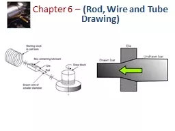
/
Chapter 6 –  (Rod, Wire and Tube Drawing) Chapter 6 –  (Rod, Wire and Tube Drawing)

Chapter 6 – (Rod, Wire and Tube Drawing) - PowerPoint Presentation

luanne-stotts
luanne-stotts . @luanne-stotts
Follow
347 views
Uploaded On 2019-03-01

Chapter 6 – (Rod, Wire and Tube Drawing) - PPT Presentation

Introduction Drawing is an operation in which the crosssectional area of a bar or tube is reduced or changed in shape by pulling it through a converging die dies are usually tapered The drawing process is somewhat similar to extrusion except that in drawing the bar is under tension w ID: 754487

wire drawing surface die drawing wire die surface bar rod diameter process mandrel cross force stock tube draw work

Share:

Link:

Embed:

Download Presentation from below link

Download Presentation The PPT/PDF document "Chapter 6 – (Rod, Wire and Tube Drawi..." is the property of its rightful owner. Permission is granted to download and print the materials on this web site for personal, non-commercial use only, and to display it on your personal computer provided you do not modify the materials and that you retain all copyright notices contained in the materials. By downloading content from our website, you accept the terms of this agreement.


Presentation Transcript

Slide1

Chapter 6 –

(Rod, Wire and Tube Drawing)Slide2

IntroductionDrawing is an operation in which the cross-sectional area of a bar or tube is reduced or changed in shape by pulling it through a converging die (dies are usually tapered).The drawing process is somewhat similar to extrusion, except that in drawing, the bar is under tension, whereas in extrusion it is under compression.Slide3

Although drawing applies tensile stress, compression also plays a significant role since metal is squeezed as it passes through die opening.Rod and wire drawing are generally finishing process, and the product is either used as produced or is further processed into other shapes, such as by bending or machining.Rods are used for various applications, such as small pistons, structural members, shafts, spindles, and as raw material for making fasteners such as bolt and screws.

Wire and wire product have a wide range of applications, such as electrical wiring, electrical equipment's, cables, springs, fencing, welding electrodes and shopping carts.Wire diameter may be as small as 0.025 mm

IntroductionSlide4

Rod productsSlide5

Wire productsSlide6

The concept of drawing involves pulling wire, rod, or bar though a die, or converging channel to decrease cross-sectional area in increase length.In the majority of the cases the cross section is circular, although none-circular cross sections may be drawn/ or created by drawing.In a comparison to rolling, drawing offersMuch better dimensional control.

Lower capital equipment cost.And extension to small cross sections.In comparison to extrusion, drawing offers

Continuous processing.Lower equipment cost.And extension to small cross sections.

DrawingSlide7

DrawingLarge quantities of wires, rods, tubes and other sections are produced by drawing process which is basically a cold

working process (Drawing is usually performed at room temperature, thus classified a cold working process, but it may be performed at elevated temperatures for large wires to reduce forces).

In this process the material is pulled through a die in order to reduce it to the desired shape and size.In a typical wire drawing operation, once

the wire is

gripped and pulled

to pass

through the opening of

the die, its diameter reduced to the desired one.Slide8

Cold drawing propertiesImproved Size and Section

Tighter size & section tolerances Dimensional consistency within each bar Dimensional consistency from bar to bar

Improved Surface Finish / Reduces surface machiningImproved Straightness Improved Cost Effectiveness / Production of Precision Shapes to Precision Tolerances

Increased

Mechanical Properties / Can reduce the need for hardening.

Yield strength

Tensile

strength

HardnessSlide9

Wire Drawing vs. Bar DrawingDifference between bar drawing and wire drawing is stock size

Bar drawing - Large diameter bar and rod stock (bar drawing usually involves stock that is too large in cross section to be coiled. Round bar stock may be 1 to 10 cm in diameter or even larger)Wire drawing

- Small diameter stock - wire sizes down to 0.025 mm (0.001 in.) are possibleAlthough the mechanics are the same, the methods, equipment.Slide10

Drawing Practice and ProductsDrawing practice:– Usually performed as cold working

– Most frequently used for round cross-sections• Products:– Wire: electrical wire; wire stock for fences, coat hangers, and shopping carts – Rod stock : for nails, screws, rivets, and springs

– Bar stock: metal bars for machining, forging, and other processesSlide11

Why not simply stretch wire, rod or bar?It can be argued, at least in principle, that some of the objectives of drawing could be achieved by simply stretching the wire with a pulling force.The cross section could be reduced and elongation accomplished, but dies would not be needed and the friction and metal flow issues presented by die could be a voided. The principle problem with just stretching the wire with a pulling force is the necking phenomena. Basically, after a certain amount of uniform stretching, all further elongation will be concentrated at a single location ( a neck), which will rapidly thin and break.

This occurs because the decrease in cross-sectional area eventually weakens wire more than any strengthening that occurs by work hardening.

How dose drawing workSlide12

Simple explanation of drawing process.In the drawing process, a pulling force and a pressure force from the die, combine to cause the wire to extend and reduce in cross-sectional area, while passing through the die as shown in the figure :

How dose drawing workSlide13

Because of this combined effect , the pulling force or drawing force is less than the force that would cause the wire to stretch, or neck and break downstream from the die.On the other hand, if a reduction too large in cross-sectional area is attempted at the die, the drawing force may break the wire.In commercial practice, engineering pulling loads are rarely above 60% of the as-drawn strength, and the area reduction in a single drawing pass is rarely above 30% or 35%, and is often much lower.

A particular common reduction in none ferrous drawing is the American Wire Gage (AWG) number, or about 20.7%. So many drawing passes are needed to achieve large overall reduction

How dose drawing workSlide14

Wire DrawingWire drawing involves stock that can be easily coiled and subjected to sequential or tandem drawing operations with as many as a dozen or more draws occurring with a given drawing machine. Each drawing operation or “pass” will involve delivery of the wire to the die from a coil on capstan OR drum, passage through the die, and take-up on a capstan that pulls the wire through the dieContinuous

drawing machines consisting of multiple draw dies (typically 4 to 12) separated by accumulating drumsEach drum (capstan) provides proper force to draw wire stock through upstream dieEach

die provides a small reduction, so desired total reduction is achieved by the series of dies.Slide15

Fine wire drawing typically refers to round wire with a diameter of less than 0.1 mm.Ultra fine wire drawing typically refers to round wire as fine as 0.0025 mm in diameter.

Wire DrawingSlide16

Annealing before each drawing operation permits large area reduction (Annealing sometimes required between dies to relieve work hardening). Because of the strain hardening, intermediate annealing between passes may be necessary in cold drawing in order to maintain sufficient ductility to the material and avoid failure. Tungsten Carbide dies are used to for drawing hard wires

, and diamond dies is the choice for fine wires.Wire DrawingSlide17

Bar DrawingBar drawing usually involves stock that is too large in cross section, and hence must be drawn straight.Round bar stock may be 1 to 10 cm in diameter and even larger.

Accomplished as a single-draft operation - the stock is pulled through one die openingBeginning

stock has large diameter and is a straight cylinder

Hydraulically operated draw bench for drawing

metal barsSlide18

The reduction in area is usually restricted to 20 to 50%, because greater reductions would exceed the tensile strength of the material, depending on its ductility. To achieve a certain size or shape multiple passes through progressively smaller dies or intermediate anneals may be required

Bar DrawingSlide19

Tubes produced by extrusion or other process (such as shape rolling)Also tubes can be reduced in thickness or diameter by tube drawing.The shape of tubes can be changed by using dies and mandrels with various profiles

Tub DrawingSlide20

Tube drawing is also similar to wire drawing, except that a mandrel of appropriate diameter is required to form the internal hole.Here three arrangements are shown in figure (a) with a floating plug and (b) fixe plug drawing(c) with a moving mandrel

Tube drawingSlide21

Fixed plug drawingThis is the oldest tube drawing method.Fixed plug drawing, also known as stationary mandrel drawing, uses a mandrel at the end of the die to shape the ID of the tube.

This process is slow and the area reductions are limited (lengths of tubes are limited), but it gives the best inner surface finish of any of the processes. Slide22

Floating plug drawingFloating plug drawing, also known as floating mandrel drawing, uses a mandrel that is not anchored

whatsoever to shape the ID of the tube. The mandrel is held in by the friction forces between the mandrel and the tube. The greatest advantage of this that it can be used on extremely long lengths, sometimes up

to 1,000 feet (300 m). The disadvantage is it requires a precise design otherwise it will give inadequate results. This process is often used for oil- tubingSlide23

Floating plug drawingSlide24

Is the process that draws the tube with a mandrel inside the tube; the mandrel is drawn with the tube (moving mandrel).  Tubes as large as (30 m)in diameter can be drawn. The advantage to this process is that the mandrel defines the ID and the

surface finish. The disadvantages are that lengths are limited by the length of the mandrel, usually no more than 100 feet (30 m), and that a second operation is required to remove the mandrel, called reeling

. This type of process is usually used on heavy walled or small ID tubes. Common applications include super-high pressure tubing and hydraulic tubing This process is also use for precision manufacturing of trombone hand slides

Moving mandrel drawingSlide25

Moving mandrel drawingAlso known as semi-floating mandrel drawing, is a mix between floating plug drawing and fixed plug drawing. The mandrel is allowed to float at the end of tube, but it still

anchored. This process gives similar results to the floating plug process, except that it is designed for multiple diameter of straight tubes. It gives a better inner surface finish than rod drawing.Slide26

Annealing – to increase ductility of stockAnnealing: This is a thermal treatment generally used to soften

the material being drawn, to modify the microstructure, the mechanical properties and the machining characteristics of the steel and/or to remove internal stresses in the product. Depending on the desired characteristics of the finished product, annealing may be used before, during (between passes) or after the cold drawing operation, depending on material requirements.

Preparation of the Work for

Wire or Bar DrawingSlide27

Cleaning - To prevent damage to work surface and draw die (Abrasive scale (iron oxide) on the surface of the hot rolled rough stock is

removed) it is done by pickling process.Pointing – to reduce diameter of starting end to allow insertion through draw die (Several inches of the lead ends of the bar or coil are reduced in size by swaging ,so

that it can pass freely through the drawing die. Note: This is done because the die opening is always smaller than the original bar or coil section

size

) and also to prevent die from wearing.

Coating

: The

surface of the bar or coil is coated with a drawing lubricant to aid cold drawing.

Preparation of the Work for

Wire or Bar Drawing

Raw Stock

: Hot rolled steel bar or

rod coils

are used as

raw material. Because the

hot rolled products are produced

at elevated

temperatures (1700

– 2200 i.e

. hot rolling), they

generally have

a rough and scaled surface

and may

also exhibit variations in

section and

size.Slide28

LubricationProper lubrication is important in drawing operations.The basic methods of lubrication used in wire drawing are:

Dry drawing : in dry drawing, the surface of the wire is coated with various lubricants, depending on the strength and frictional characteristics of the material. The rod to be drawn is first surface treated by pickling, which removes the surface scale that could lead to surface defects and considerably reduce die life (because of it’s abrasiveness). The bar then goes through a box (stuffing box) filled with soap powder to coat it Pickling is a metal surface treatment used to remove impurities,

contaminants, rust or scale from ferrous metals, copper, and aluminum alloys.

A

solution

called

pickle

liquor

, which contains 

strong acids

, is used to remove the surface impurities. It is commonly used to descale or clean 

steel


in various

 steelmaking processesSlide29

Wet drawing : in wet drawing, the dies and rod are completely immersed in a lubricant. Typical lubricants include oils and emulsion (containing fatty or chlorinated additives) and various chemical compounds.Metal coating : for high - strength materials, such as steels, stainless steels, and high-temperature alloys, the surface of the rod may be coated with a softer metal or with conversion coating[is a protective surface layer on a metal that is created by chemical reaction between the metal and a chemical solution. 

They are used for corrosion protection, to add decorative color and as paint primers]. Conversion coatings may consists of sulfate oxalate coatings on the rod, which typically are then coated with soap, as a lubricant.Copper or tin can be chemically deposited as a thin layer on surface of the metal, whereby it acts as a solid lubricantPolymers may also

be used as a solid lubricants, such as in drawing titaniumLubricationSlide30

Features of a Draw DieEntry region - funnels lubricant into the die to prevent scoring of work and die

Approach - cone-shaped region where drawing occursBearing surface (land) - determines final stock size. The purpose of the land is to size, that is, to set the final diameter of the product

Back relief - exit zone – if the exit of die bearing has a sharp edge, this can shave the wire. This will produce metal particles, dust or fines, which willPollute drawing lubricantBlock the entrance of the next dieSlide31

Back reliefThe friction against sharp edge also imparts vibration to the wire, which can be transmitted through the machine. The negative results of this are:Abnormal wear of the diePoor wire quality

Numerous wire breaks

Features of a Draw Die

To avoid this sharp edge, it is necessary to produce A well smooth transition zone between the bearing and the exit zoneSlide32

Die materialsDie materials for drawing are generally alloy tool steels, carbides, or diamond.For drawing fine wires the die may be diamond, either a single crystal or a polycrystalline diamond.Carbide and diamond dies are made as inserts or nibs, which are then supported in a steel casting as shown:Slide33

A typical wear pattern on a drawing die is shown below.The die wear is highest at the entry. Although the pressure is highest in this region and may be partially reasonable for wear of die.

Die WearSlide34

Other factors that are involved in wearing of die include:Variations in the diameter of the entering wire.Vibration, which subjects the die-entry contact zone to fluctuating stresses

The presence of abrasive scale on the surface of entering wire.

Die WearSlide35

EquipmentDrawing equipment can be of several designs. These designs can be classified into two basic types; Draw bench, and Bull block:

A draw bench : A draw bench uses a single die and the pulling force is supplied by a chain drive or by hydraulic means. Draw bench is used for single length drawing of rod or tube with diameter greater than 20mm (may be 1 to 10 cm in diameter and even larger). Length can be as much as 30 m

. similar to a long horizontal tensile testing machine but with hydraulic or chain-drive mechanism, is used for single draws of straight rods with large cross sections and for tubes with length up to 30 m.Bull block : smaller cross sections are usually drawn by a bull block, which is basically a rotating drum around which wire is wrapped. The tension in the setup provides the force required to draw the wireSlide36

A draw bench

uses

a single die and the pulling force is supplied by a chain drive or by hydraulic means. Draw bench is used for single length drawing of rod or tube with diameter greater than 20mm. Length can be as much as 30 m

 Drawing equipment can be of several designs. These designs can be classified into two basic

types

Draw bench

for rod and tube

and

Bull

block for wire

EquipmentSlide37

Draw benchSlide38

Bull block Slide39

Drawing DefectsDefects in drawing are similar to those observed in extrusion especially center cracking.The factors influencing center cracking are:The tendency for cracking increase with increasing die angle.

Decreasing reduction per pass.FrictionThe presence of inclusions in the material. A type of surface defect in drawing is the formation of

seams. These are longitudinal scratches or folds in the material which can open up during subsequent forming operation, such as by upsetting, heading, thread rolling, or by bending of the wire or rod.Slide40

Because of inhomogeneous deformation that the material undergoes, a cold drawn rod, wire, or tube usually contains residual stresses.Typically a wide range of residual stresses can be present within the rod in three principles directions :Transverse directionLongitudinal direction.Radial direction.

Residual stress in drawing operation

Drawing DefectsSlide41

For very light reductions, the surface residual stresses are compressive. Note that light reductions are equivalent to shot peening or surface rolling which induce compressive residual stresses on surface, thus improving fatigue life.Residual stress can be significant in stress application causing cracking or in warping of the component when a layer is subsequently removed, as by machining or grinding

Residual stress in drawing operationSlide42

shot peeningShot peening is a cold working process used to produce a compressive residual stress layer and modify mechanical properties of 

metals. It entails impacting a surface with shot (round metallic, glass, or ceramic particles) with force sufficient to create plastic deformationSlide43

Mechanics of rod and wire drawingThe major variables in drawing process are:The reduction in cross-sectional area

Die angleFriction also plays a major roleSlide44

The drawing stress, σd, for the simplest case of ideal deformation-no strain hardening ( that is no friction or redundant work ) is obtained by :

For the material that exhibits strain hardening with the true-stress-strain behavior, Y is replaced by an average flow stress

Ȳ:

Where

Y

is the yield stress of the material

The quantity,

Ȳ, is obtained from the expression:

Where Ȳ

is

the

average flow stress

Idea drawing force-with no frictionSlide45

Idea drawing force-with no frictionThe ideal drawing force ( that is no friction or redundant work ) is obtained by :Where

iis the average flow stress and can be obtained by :A0: is the initial cross sectional area.A

f: is the final cross sectional area.K is the stress (strength) coefficient, n is the strain hardening (work hardening) exponentSlide46

Friction at the die-workpiece interface increases the drawing force because work has to be supplied externally to overcome friction.

Idea drawing force-with friction

The drawing stress with friction is obtained by following expression: .Slide47

Noting that the compressive stresses in the two directions are equal to p, the die pressure along the die contact length can be obtained:

Die pressure

Y

f

Y

f

:is the flow stress ,

σ

:is the tensile stress in the deformation zone.Slide48

Example A round rod of annealed 302 stainless steel is being drawn from a diameter of 10 mm to 8 mm at s speed of 0.5m/s. assume that frictional and redundant work together constitute 40% of the ideal work of the deformation.Calculate the power required for this operation?

Calculate the die pressure at the exit of the die? Slide49

Comparison of bulk deformation processesSlide50

Comparison of bulk deformation processesSlide51

Comparison of bulk deformation processes