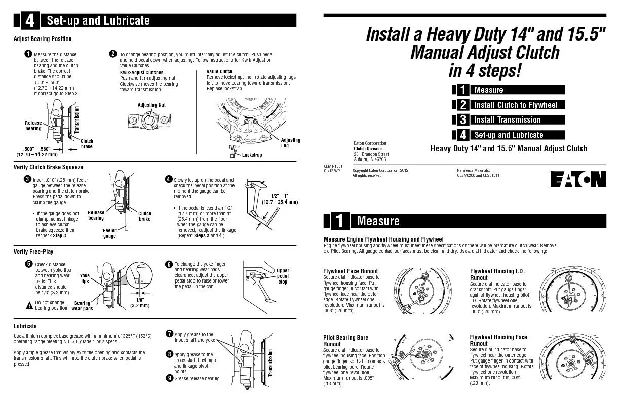
/
Engine flywheel housing and flywheel must meet these specifications or Engine flywheel housing and flywheel must meet these specifications or

Engine flywheel housing and flywheel must meet these specifications or - PDF document

luanne-stotts
luanne-stotts . @luanne-stotts
Follow
404 views
Uploaded On 2016-05-06

Engine flywheel housing and flywheel must meet these specifications or - PPT Presentation

Setup and Lubricate Flywheel Face Runout Secure dial indicator base to flywheel housing face Put Pilot Bearing Bore Runout Secure dial indicator base to flywheel housing face Position Flywheel Hous ID: 308007

Set-up and Lubricate Flywheel Face

Share:

Link:

Embed:

Download Presentation from below link

Download Pdf The PPT/PDF document "Engine flywheel housing and flywheel mus..." is the property of its rightful owner. Permission is granted to download and print the materials on this web site for personal, non-commercial use only, and to display it on your personal computer provided you do not modify the materials and that you retain all copyright notices contained in the materials. By downloading content from our website, you accept the terms of this agreement.


Presentation Transcript

Engine flywheel housing and flywheel must meet these specifications or there will be premature clutch wear. Remove old Pilot Bearing. All gauge contact surfaces must be clean and dry. Use a dial indicator and check the following: Set-up and Lubricate Flywheel Face Runout Secure dial indicator base to flywheel housing face. Put Pilot Bearing Bore Runout Secure dial indicator base to flywheel housing face. Position Flywheel Housing I.D. Runout Secure dial indicator base to crankshaft. Put gauge finger Flywheel Housing Face Runout Secure dial indicator base to flywheel near the outer edge. Verify Clutch Brake Squeeze 8 Apply grease to the cross shaft bushings To change bearing position, you must internally adjust the clutch. Push pedal Value Clutches. • If the gauge does not • If the pedal is less than 1/2" To change the yoke finger 4 5 6 Check distance 4 1 Measure 1 Install Clutch to Flywheel 2 Install Transmission 3 Set-up and Lubricate 4 Verify Free-Play 1/2" – 1" (12.7 – 25.4 mm) Install a Heavy Duty 14" and 15.5"Manual Adjust Clutchin 4 steps!Heavy Duty 14" and 15.5" Manual Adjust Clutch Transmission 1 Feeler gauge Release bearing Clutch brake Upper pedal stop Use a lithium complex base grease with a minimum of 325°F (163°C) Eaton Corporation Clutch Division Reference Materials: All rights reserved.CLMT-1351 Measure the distance Transmission Clutch brake .500" – .560" (12.70 – 14.22 mm) TO TURN DEPRESS BOLT Adjusting Nut Yoke Do not change Lockstrap Adjusting Value Clutch 9 Grease release bearing Super-duty clutch only: Install Transmission Check Transmission For Wear Fasten Transmission To Flywheel HousingTransmission installation and clutch set-up procedures gear. Be sure new forward and rotating the output shaft. Do not use excessive force. Do not let starting with a lower bolt. Torque Turn intermediate 7" (8-spring) 8.5" (10-spring) 10" • 7 spring • 9-spring (Mack engines only) cover. Flywheel Verify bearing position is from cover. (68 kg). Avoid the risk of injury. Use proper equipment IMPORTANT: discs from sliding freely, causing poor clutch release (clutch drag). Slide discs full length of shaft to check for twisted shaft splines. Transmission wear prematurely.Release YokeWorn fingers can interference when Wear (roughness) starting with a lower bolt. Torque