/
WATER CLOSET SUPPORTS TECHNICAL DATA CUSTOMER DRIVEN SMITH Smith engineers have developed WATER CLOSET SUPPORTS TECHNICAL DATA CUSTOMER DRIVEN SMITH Smith engineers have developed

WATER CLOSET SUPPORTS TECHNICAL DATA CUSTOMER DRIVEN SMITH Smith engineers have developed - PDF document

luanne-stotts
luanne-stotts . @luanne-stotts
Follow
587 views
Uploaded On 2014-10-28

WATER CLOSET SUPPORTS TECHNICAL DATA CUSTOMER DRIVEN SMITH Smith engineers have developed - PPT Presentation

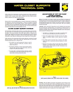
Supports have been designed for water closets urinals lavatories sinks drinking fountains and many special purpose hospital institutional and industrial plumbing 64257xtures DEFINITION Fixtures which are wall mounted and have no external contact wit ID: 8637

Supports have been designed

Share:

Link:

Embed:

Download Presentation from below link

Download Pdf The PPT/PDF document "WATER CLOSET SUPPORTS TECHNICAL DATA CUS..." is the property of its rightful owner. Permission is granted to download and print the materials on this web site for personal, non-commercial use only, and to display it on your personal computer provided you do not modify the materials and that you retain all copyright notices contained in the materials. By downloading content from our website, you accept the terms of this agreement.


Presentation Transcript

WATER CLOSET SUPPORTSTECHNICAL DATA SMITH¨ mounting all types of "off the ßoor" Þxtures. Supports have been designed for waterare classiÞed as "off the ßoor plumbing Þxtures." Fixtures so mounted are supporteddeveloped. Thus, when mounting "off the floor" water closets, a complete unit isthe code ofÞcial is assured that Þttings used with supportsis assured that the system uses a minimum of ßoor space, with all the necessarycontractor is assured a simple, fast and efÞcient installation. Off the ßoor systems Fig. 1INSTALLING PIPING FOR FLOOR MOUNTED FIXTURESFig. 2INSTALLING PIPING FOR "OFF THE FLOOR" FIXTURESSanitation--After the building is turned over to the owners, cost for cleaning in thearea under the "off the ßoor" water closets is considerably less than in similar areaswhich have ßoor mounted Þxtures. A mop is easily passed under off the ßoor Þxturesthoroughly cleaning the floor beneath as compared to the very difficult task ofcleaning around and in back of floor mounted water closets. Cleaning costs arereduced, and the toilet room is maintained in a more sanitary condition. ଀\b଀ሀ #/,;@7,\rᴀ6;3,;*655,*;0650::,+&#x-210;0;/-3669465;,+)(*26;3,;*36:,;:\t#/,\rᴀ*655,*;0650:(505;,.9(350773,\n*67305.�/6:,3,5.;/0::7,*0-0,+)@;/,+04,5:065\t#/,\rᴀ*(5(**6446+(;,(:4(33,9+04,5:065;/(5;/,;@7,\r*655,*;065\t ᜀ᠀ᰀሀᜀᘀ\n᐀\f᐀ᜀᬀ฀ᰀᜀᴀᰀ᐀฀ᰀ\fᜀᘀᘀ฀\fᰀሀᜀᘀᬀ ᠀69:,怀0;/-3669465;,+)(*26;3,;*36:,;:\t!,-,9;679,=06:7(.,-697967,9+04,5:065(5+*67305.(+1:;4,5;\tḀ0773,3,5.;/:(=(03()3,(9,(3:630:;,+\t ᘀᜀᰀ฀\t#/,ༀȀ(+1:;()3,*67305.0:796=0+,+&#x-110;0;/=,9;0*(3:36;;,+,(9:&#x-110;/0*/7,940;(\f\n\rȀ(+1:;4,5;769+6�5-69=(90(;06505-050:/,+-3669/,0./;\t ᘀᜀᰀ฀\t#/,ༀȀ(+1:;()3,*67305.0:796=0+,+�0;/=,9;0*(3:36;;,+,(9:�/0*/7,940;(\f\n\rȀ(+1:;4,5;769+6�5-69=(90(;06505-050:/,+-3669/,0./;\t ᰀἀ᠀฀ᘀᜀЀԀ\f᐀ᜀᬀ฀ᰀᜀᴀᰀ᐀฀ᰀ\fᜀᘀᘀ฀\fᰀሀᜀᘀ \fᜀᔀ᠀\n\fᰀༀሀḀᰀᴀᨀ฀ᬀᴀ᠀᠀ᜀᨀᰀᬀ"40;/*647(*;-0?;9,:7769;:&#x-220;0;/&#x-220;(:;,-0;;05.:(9,+,:0.5,+:7,*0-0*(33@-6905:;(33(;065&#x-220;/,9,565\b(+1:;()3,=,9;0*(3-0;;05.:(9,:0;()3,-69*65:;9*;0659,809,4,5;:(5+405044707,:7(*,0:6-7904,*65:0+,9(;065\t#/,:,:7769;:(9,(=(03()3,05)6;/6--:,;(5+*,5;,9305,&#x-400;(:;,;@7,\t#/,6--:,;&#x-400;(:;,;@7, -,(;9,:(5():63;,405044*,5;,9;6)(*2+04,5:065(5+0:(99(5.,+�0;/=,9;0*(3=,5;*655,*;0654(205.0;:0;()3,-6943;0\b:;69@05:;(33(;065\t#/,*,5;,9305,�(:;,;@7, +6,:56;/(=,;/,=,5;*655,*;065(5+0:3040;,+;6:05.3,:;69@05:;(33(;065:\t#/,,?;,5:0656-;/,=,9;0*(3�(:;,305,0:;/,:;(*2=,5;\t᐀6;/;@7,:(9,(=(03()3,-69:07/651,;69)36᐀6;*36:,;(7730*(;065:\t ฀Ȁᴀ05044:/6�50:(;;(05,+:05.!,.3(93@᠀950:/,+ጀ᐀"Ḁ0773,(5+ጀ+1:;\b;6\b%(33ᔀ67305.\tጀ):63;,ᴀ050446-\f\f\n\rȀ0:(=(03()3,:05.:/69;);;,5+50773,܀3,::ጀ+1:\b;6\b%(33ᔀ67305.\t ᠀(*,᠀(33366205.05;6*36:,;6;3,;*655,*;065\tᬀ-*655,*;0650:65;/,3,-;:0+,6-;/,=,9;0*(3:;(*2܀0;0:(3,-;/(5+:7769;\tᬀ-65;/,90./;:0+,܀0;0:(90./;/(5+:7769;\t ጀ33*647(*;:,90,:-0?;9,:7769;:(9,(=(03()3,�0;/(?030(9@053,;:\t#/,6--:,;:,90,:(9,(=(03()3,�0;/,0;/,9(:(50;(9@:�,,7;@7,053,;69(-3(;)6::;@7,*655,*;065\t#/,*,5;,9305,�(:;,;@7,:7769;:(9,(=(03()3,&#x-110;0;/653@(-3(;)6::;@7,053,;*655,*;065\t᐀6;/053,;;@7,:(9,(=(03()3,05\f\f\nༀ܀\f\f\n\r69\rȀ;/9,(+\tጀ\rȀ*(32(5+56\b/)*655,*;065:(9,(=(03()3,-69;/,:(50;(9@:�,,7;@7,053,;\t \r฀ᰀ฀ᨀᔀሀᘀሀᘀက᐀฀ༀᰀᜀᨀᨀሀကᄀᰀᄀ\nᘀ\r\fᜀᔀ᠀\n\fᰀༀሀᰀᰀሀᘀကᬀ ଀\nᬀ฀ᬀᴀ᠀᠀ᜀᨀᰀ\n\rጀᴀᬀᰀᔀ฀ᘀᰀ ጀ+1:;4,5;3040;(;065:(9,:/6�5()6=,-69)6;/65,(5+;�6\b769*65:;9*;065\tᔀሀᘀሀᔀᴀᔀᬀ᠀\n\f฀ᨀ฀ᤀᴀሀᨀ฀ᔀ฀ᘀᰀᬀༀᜀᨀ\fᜀᔀ᠀\n\fᰀༀሀḀᰀᴀᨀ฀ᬀᴀ᠀᠀ᜀᨀᰀᬀ\rᜀᴀ଀᐀฀\fᜀᔀ᠀\n\fᰀᜀༀༀᬀ฀ᰀༀሀᰀᰀሀᘀက᠀0.\t଀ༀ\f଀ᘀ':/6ᘀ505:;(33,+05(65,\b769;@7,-3669*65:;9*;065\tᘀ04,5:065:(773@;6ༀȀ:0A,653@\tᬀሀᘀက᐀฀\fᜀᔀ᠀\n\fᰀᜀༀༀᬀ฀ᰀༀሀᰀᰀሀᘀက᠀0.\t଀ༀ\f଀!':/6଀505:;(33,+05(65,\b769;@7,-3669*65:;9*;065\tᘀ04,5:065:(773@;6ༀȀ:0A,653@\t؀฀B%ᨀᜀḀ$"ᜀᘀ%ᬀ#ᨀᨀ$᐀̀" ᬀᤀἀ#᠀ᬀ##ᬀḀᤀ\t ᐀(:,:7769;4:;),:,*9,3@(5*/69,+;6(90.0+-3669(5+\n696;/,990.0+:)\b:;9*;9,က0;/ЀༀԀ\f\n\rB)63;:-950:/,+)@6;/,9:\t Ȁᘀᜀᰀ฀\t",,7(.,଀\b଀ᄀ-69Ḁ0773,3,5.;/:(=(03()3,\t ᘀᜀᰀ฀\tᔀ67305.:/63+,?;,5+က\n\fᄀ),@65+-050:/,+ᄀ(33\tᰀἀ᠀฀̀ᔀ\b܀ᔀᰀἀ"ᜀ#ἀ$#ᰀᜀ#ᔀἀḀḀᜀᔀ#ἀ!᠀ἀ!$"ᜀ%ᬀ#ᨀ"#ጀᬀḀᰀᜀ"""#ᜀᜀᰀ᠀ᬀ&#$!ᜀ"ᰀἀ᠀฀̀ᔀ\b؀ᔀᰀἀ"ᜀ#ἀ$#ᰀᜀ#ᔀἀḀḀᜀᔀ#ἀ!᠀ἀ!$"ᜀ%ᬀ#ᨀ"#ጀᬀḀᰀᜀ"""#ᜀᜀᰀ᠀ᬀ&#$!ᜀ" ᰀἀ᠀฀Ԁᔀ\f᐀ᜀᬀ฀ᰀᜀᴀᰀ᐀฀ᰀ\fᜀᘀᘀ฀\fᰀሀᜀᘀ ᔀሀᘀᔀ\nḀ\f VENT LOCATIONS ON VERTICALADJUSTABLE FITTING All Smith vertical adjustable Þttings without side inlets are regularly furnished with a All vertical adjustable Þttings can be supplied with either a -N15 (1 1/2") or -N2 (2") AUXILIARY INLET CONNECTIONSUFFIX -N15SUFFIX -N2 Vent When\rLeft Hand InletWhen\r VentAux.\r DIMENSION - ADJUS-TO-WALL TYPEOUTLET CONNECTIONThe Smith Adjus-to-Wall outlet connection provides adjustment at the face of the walldimension is measured from the front of the face plate to the face of the Þnishedwall. To properly determine the length of nipple required, deduct 1" from the dimension. The Adjus-to-Wall coupling will provide 1/2" horizontal adjustment ineither direction with the coupling extended 5/16" past face of the Þnished wall. Face Plate c Finished Wall ABS Nipple ABS Coupling 2 1/2 NOTE: When nipple lengths between 3 1/4"and 8 1/4" are speciÞed, the 8 1/4" nipple will be *ABS (Regularly Furnished) other lengths PVC. NIPPLELENGTH MIN MAX2 1/2 2 1/4 3 1/4*3 1/4 3 4*8 1/4 8 910 9 3/4 10 3/412 11 3/4 12 3/415 14 3/4 15 3/418 17 3/4 18 3/4 ABS CouplingFace\rABS Nipple with\rCoupling\rProtector Every Smith Adjus-to-Wall outlet connection is furnished with a polystyrene couplingCOUPLING PROTECTOR RECOMMENDED SETTING OF CLOSET OUTLETCONNECTION AND FIXTURE STUDSManufacturers have slight differences in the depth of the closet horn and flangeextend5/16" beyond face of finished wall (Dimension "R") and the fixture studs 2 1/4"(dimension "X"). For exact dimensions, please use the formulas below: *D = 1/2" for felt gasket and 3/8" for neoprene gasket. Bearing nuts and washers must be set to take full loading from the Þxture Gasket* R S Lug Supporting Stud 1/16DETAIL B NOTE: Vent andauxiliary inlet, are c c c c CUSTOMER\rDRIVEN SMITH¨ SELECTION OF VERTICAL FITTING WITH SIDE INLETS The vent is always located on the same side as the inlet on a single inlet stack Þ tting. StackLEFT HANDRIGHT HAND Two Side Inlets TYPICAL INSTALLATIONs SPACE REQUIREMENTS FOR SINGLE ANDDOUBLE HORIZONTAL SUPPORTS Base support mustbe securely anchor-ed to a rigid floorand/or other rigidsub-structure with1/2" bolts furnishedby others. and Adjus-to-Wall Coupling.Shown is the minimum pipe space required for a single and doublehorizontal support. HORIZONTAL FITTINGS Fig. 0210LYFig. 0250RY STACKFig. 0210RY of the room. Closet Þttings to the left of the stack are left hand Þttings. Closet Þttings AND FINISHED FLOOR MAX 9sCut Off Tabs MAX 9ROUGH SLAB FINISHED FLOOR FILL Fig. 0200 SERIES SHALLOW ROUGH-IN TYPEThe face plate is designed for one-pour construction, consisting of a single slab withÞll and 1/4" Þnished material.Cut-off grooves provided on 0200 Series face plates. This allows removal of tabsto accommodate 5" or 4 1/4" minimum roughs. FITTINGS WITH SIDE INLETS Siphon Jet--The location of the side inlet is determined by the center of the closetoutlet to the Þnished ßoor plus the thickness of the Þnished ßoor materials. This will(0200 Series) or one-pour slab construction, the side inlet should always set on theslab ßoor.--The location of the side inlet should be set in the lowest position fromcenter line of the closet outlet to center line of side inlet. 3s3 MIN LugSub Floor s3 MINs3 MIN ROUGH FLOOR SLAB FIXTURE SIDE CUSTOMER DRIVEN SMITH¨ Battery of horizontal Þttings with adjustable closet supports connected to a stackSIPHON JETBLOWOUT The architects construction design and physical layout of the toilet room dictates the type of Þttings that can be selected by the engineer for battery installations. The engineers Slip gauge over studs and hold tight against wall.Check for plumb and level. Adjust bearing washersand nuts to fit tight against back of gauge. Makenecessary adjustments for alignment of studs.Hold gauge tight against wall and adjust outletcoupling ßush with pad corresponding to closet hornHold gauge tight against bearing nuts and washers,and mark cut-off point of studs flush with gaugeextensions. Remove gauge and cut off studs.Install bowl. Base support must besecurely anchored to arigid floor and/or otherrigid substructure with 1/2"bolts furnished by others. Fig. 0240RYFig. 0220RYFig. 0220RYFig. 0210LYFig. 0210RYFig. 0220RY DRIVEN SMITH¨