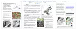
/
H ow will large anthropogenic valley-fills in Central Appalachian headwaters erode? H ow will large anthropogenic valley-fills in Central Appalachian headwaters erode?

H ow will large anthropogenic valley-fills in Central Appalachian headwaters erode? - PowerPoint Presentation

marina-yarberry
marina-yarberry . @marina-yarberry
Follow
383 views
Uploaded On 2018-10-11

H ow will large anthropogenic valley-fills in Central Appalachian headwaters erode? - PPT Presentation

Over 6000 anthropogenic valleyfills have been created by mountaintop removalvalleyfill mining within the headwaters of Central Appalachia MTRVF Fig 1 EPA 2011 An individual valleyfill can have a volume of up to ID: 687928

west valley virginia fill valley west fill virginia fills fig model caesar years 1000 lidar figure catchment gully drainage

Share:

Link:

Embed:

Download Presentation from below link

Download Presentation The PPT/PDF document "H ow will large anthropogenic valley-fil..." is the property of its rightful owner. Permission is granted to download and print the materials on this web site for personal, non-commercial use only, and to display it on your personal computer provided you do not modify the materials and that you retain all copyright notices contained in the materials. By downloading content from our website, you accept the terms of this agreement.


Presentation Transcript

Slide1

How will large anthropogenic valley-fills in Central Appalachian headwaters erode?

Over 6000 anthropogenic valley-fills have been created by mountaintop removal/valley-fill mining within the headwaters of Central Appalachia (MTR/VF) (Fig. 1) (EPA, 2011).An individual valley-fill can have a volume of up to 200 million m3 (Ross et al., 2016) and a thickness of up to 120 m (Michael and Superfesky, 2007).The majority of valley-fills are constructed by dry downslope grain flow from mine spoil dumped from the head of a valley. Valley-fills are created as a variance to the Surface Mining Control and Reclamation Act’s requirement of approximate original contour. There is no requirement for long-term maintenance in current regulations. No guidance exists from government or industry on long-term rate of erosion or dominant erosional processes.MTR/VF landscapes are a dramatic rearrangement of topography that has never been studied in the field by a geomorphologist (Fig. 2).An anthropogenic valley-fill landform is composed of a face, side slopes, and a constructed drainage system (Fig. 3).Gully erosion has been observed in 1 m resolution lidar imagery (Fig. 3 and 4).Valley-fills generally reside on private property owned by coal companies or land holding companies.

0

1000

years

100

200

300

400

500

600

700

800

900

0

100

200

300

400

500

600

700

800

900

1000

years

hourly average discharge (m

3

s

-1

)

hourly sediment yield (m

3

h

-1

)

Background

Methods

Access has been obtained to the newly acquired West Virginia Department of Natural Resources

elk restoration sites in Mingo and Logan Counties, West Virginia. The sites contain 43 valley-fills.

The sites are divided into four study areas: Ark, Delbarton, Scarlet North, and Whitman West,

which is shown in Fig. 5.

The study areas have very similar Middle Pennsylvanian geology with the Kanawha Formation

composing valley and slopes and the Allegheny Formation composing the ridges, if present

(

Outerbridge

, 1987).

Erosional landforms will be mapped on 15 valley-fills in the summer of 2017. Eight valley-fills

of the same construction date (2003) and a range of drainage areas (0.045 – 0.456 km

2

) have been

selected to test whether drainage area affects erosional processes on valley-fills. Seven fills

with a range of construction dates (1990-2009) and similar drainage areas (0.34 ± 0.03 km

2

) will

test whether exposure to more erosive events is

guiding the

development of erosional

landforms.

Slope

rasters

of valley-fill catchments derived from 1 m

lidar

will be used as base maps. Mapping

will be focused on valley-fill faces and side slopes. Gully erosion (Fig. 6), seepage erosion, and rill erosion are expected to be the processes at work. All landforms will be measured, and the location obtained with GPS. Cross-sections of any gullies or enlarged drainage ditches will be measured to estimate volume of eroded material. Causal mechanisms will be sought in field (e.g., gully from haulage road runoff in Fig. 4). Modified Wolman pebble counts will be conducted in gullies, enlarged and uneroded drainage ditches, rilled areas, and seepage faces (Kondolf, 1997). Incipient stream channel morphology will be classified using the scheme of Montgomery and Buffington (1997).Pebble count data and any observed erosional landforms will be used to parameterize the CAESAR-Lisflood landscape evolution model (Coulthard et al., 2013).CAESAR-Lisflood will be used to explore the possible long-term trajectories of several valley-fills by modeling runoff and sediment yield for 1000 years. CAESAR-Lisflood uses a hydrodynamic flow model, which can portray event-based erosion in a more physically accurate manner when compared to landscape evolution models using a steady-state flow model (Coulthard et al., 2013).CAESAR-Lisflood has previously been used to model erosion on uranium mining landforms in Australia (Hancock et al., 2015).

A preliminary 1000 year simulation was run using NOAA hourly precipitation data for Charleston, West Virginia, and an a coarse (D

50

= 32 mm), a priori grain size distribution.The hourly rainfall record of 65 years was looped to make a 1000 year record (Fig. 7).Sediment yield and discharge is measured from the catchment outlet. Sediment yield during large runoff events showed a decline over time under the same hydrologic regime. This decline coincided with a increase in median grain size along major flow paths (Fig. 8).The model showed the development of a large gully on the north side of the valley-face near the transition to the side slope. The toe of the valley-fill experienced the heaviest erosion with over 10 m of incision (Fig. 9). Beyond the valley-fill toe there was over 12 m of deposition and development of braided stream channel morphology (Fig 9).

Figure 5. 1 m lidar-derived hillshade of Whitman West study area located 4 km from Logan, West Virginia [NAVD 88, NAD83 UTM Zone 17 N]. Whitman West contains 6 of the valley-fills that have been selected for geomorphological mapping of erosional landforms. Whitman West and the other study areas were acquired by the West Virginia Department of Natural Resources for the restoration of an elk population in West Virginia. Valley-fill polygons were sourced from TAGIS (TAGIS, 2013).

Figure 6. Downslope view of a steep gully eroded into a valley-fill side slope located at Jenny Wiley State Park near Prestonsburg, Kentucky. Some sections were eroded down to bedrock. The gully was formed beside a groin drainage ditch, which is placed near the interface of the valley-fill face and side slope. Gully width is ~2 m. Photo by author.

Figure 1. Extent of mountaintop removal/valley-fill mining in Central Appalachia (modified from Miller and Zegre, 2014). This style of surface mining is almost solely practiced in Central Appalachia.

Figure 2

. 1 m transparent hillshade with underlying lidar-derived digital elevation model of MTR/VF landscape near Hampden, West Virginia [NAVD 88, NAD83, UTM Zone 17N]. Lidar sourced from West Virginia Department of Environmental Protection’s Technical Unit (TAGIS, 2013).

Figure 3

. 1 m lidar-derived hillshade of a valley-fill with labeled landform elements (black) and gullies (white). Relief from the haulage road (top right) to the valley-fill toe (bottom center) is ~235 m.

Figure 4. 1 m lidar-derived hillshade of a valley fill located in the Whitman West study area (Fig. 5) with labeled enlarged constructed drain and a gully (black). The haulage road looks to be providing runoff to the valley-fill face.

References and Acknowledgements

Figure 9. A) 1 m hillshade of input digital elevation model (DEM) of valley-fill catchment used for CAESAR-Lisflood landscape evolution modeling. The catchment area is 0.67 km2. The abrupt end to the catchment on the western edge is a product of clipping off some of the DEM, allowing water to flow out of the catchment (cannot flow through NoData pixels). B) Elevation difference of initial DEM after 1000 years of runoff and sediment transport. Bedrock that cannot be eroded under this model parameterization was modeled to be at a depth of 2 m on valley-fill side slopes. A braided channel morphology could be observed beyond the valley-fill after ~200 years of model run time. A complete parameterization of the model is available as a handout.

Figure 8. CAESAR-Lisflood predicted hourly sediment yield at the outlet of the catchment shown in Fig. 9A for 1000 years. Large flow events exerted less of an influence as time progressed, while centennial sediment yield showed a different pattern (inset). A total of 27122 m3 exited the catchment.

Figure 7. CAESAR-Lisflood predicted hourly average discharge using NOAA hourly rainfall data for Charleston, West Virginia. The 65 year record was looped to make a 1000 year record using a R script.

Miles Reed and Dr. Steve Kite

sed. yield (m

3

)

years

Coulthard

, T.J., Neal, J.C., Bates, P.D., Ramirez, J., Almeida, G.A., and Hancock, G.R., 2013, Integrating the LISFLOOD‐FP 2D hydrodynamic model with the CAESAR model: implications for modelling landscape evolution: Earth Surface Processes and Landforms, v. 38, p. 1897-1906.Kondolf, G.M., 1997, Application of the pebble count notes on purpose, method, and variants: JAWRA Journal of the American Water Resources Association, v. 33, p. 79-87.Michael, P.R., and Superfesky, M.J., 2007, Assuring Stability of Minimized Valley Fills: A Review of Potential Causes of Instability and Available Countermeasures, in Proceedings of 2007 National Meeting of the American Society of Mining and Reclamation, Gillette, Wyoming: p. 457-491.Miller, A.J., and Zégre, N.P., 2014, Mountaintop removal mining and catchment hydrology: Water, v. 6, p. 472-499.Montgomery, D.R., and Buffington, J.M., 1997, Channel-reach morphology in mountain drainage basins: Geological Society of America Bulletin, v. 109, p. 596-611.Outerbridge, W.F., 1987, The Logan plateau, a young physiographic region in West Virginia, Kentucky, Virginia, and Tennessee: U.S. Geological Survey Bulletin 1620, 26 p.Ross, M.R., McGlynn, B.L., and Bernhardt, E.S., 2016, Deep impact: Effects of mountaintop mining on surface topography, bedrock structure, and downstream waters: Environmental science & technology, v. 50, p. 2064-2074.Technical Assistance and GIS Unit (West Virginia Department of Environmental Protection), 2013, West Virginia Lidar Repository: http://tagis.dep.wv.gov/data/lidar (accessed October 2016).U.S. Environmental Protection Agency, 2011, The Effects of Mountaintop Mines and Valley Fills on Aquatic Ecosystems of the Central Appalachian Coalfields: http://ofmpub.epa.gov/eims/eimscomm.getfile?p_download_id=501593 (accessed May 2016).

Aknowledgements: Miles Reed would like to thank Dr. Steve Kite, Dr. Aaron Maxwell and Dr. Nick Zégre (West Virginia University), Dr. Chris Ryan (West Virginia Department of Natural Resources), Mr. Nick Schaer (West Virginia Department of Environmental Protection), Dr. Tom Coulthard (University of Hull), and The Greater Kanawha Valley Foundation.

@

wvgeomorph

mreed5@mix.wvu.edu

jskite@wvu.edu

Before

After 1000 years

A)

B)

Modeling with CAESAR-

Lisflood