/
Indian Institute of Technology       Hyderabad Indian Institute of Technology       Hyderabad

Indian Institute of Technology Hyderabad - PowerPoint Presentation

marina-yarberry
marina-yarberry . @marina-yarberry
Follow
392 views
Uploaded On 2016-09-05

Indian Institute of Technology Hyderabad - PPT Presentation

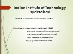
Driveline of dual clutch transmission system Submitted by Ajay Rajput me14mtech11022 Shantanu Gaikwad me14mtech11024 ID: 460985

motion equation clutch model equation motion model clutch control system elements shaft transmission synchronizer hydraulic dual flow drive differential tyre gear volumes

Share:

Link:

Embed:

Download Presentation from below link

Download Presentation The PPT/PDF document "Indian Institute of Technology Hyd..." is the property of its rightful owner. Permission is granted to download and print the materials on this web site for personal, non-commercial use only, and to display it on your personal computer provided you do not modify the materials and that you retain all copyright notices contained in the materials. By downloading content from our website, you accept the terms of this agreement.


Presentation Transcript

Slide1

Indian Institute of Technology Hyderabad

Driveline of dual clutch transmission system

Submitted by : Ajay

Rajput

(me14mtech11022)

Shantanu

Gaikwad

(me14mtech11024)

Yashdeep Nimje(me14mtech11038)

Nitin

Shelke

(me14mtech11032)

Brijesh

patel

(me14mtech11033)Slide2

Car model Slide3

Chevrolet Corsa SedanSlide4

How actually dual clutch transmission system works !! Slide5

Driving mode

POWER UPSHIFTSlide6

POWER DOWNSHIFTSlide7

VEHICLE LAUNCHSlide8

Lumped parameter model for a DCT equipped Powertrain

Fifteen degree of freedom modelSlide9

Engine, Flywheel, and

Clutch

drum model elements

By Newton second law , we get the equation of motion for each element is as follow

Equation of motion :Slide10

Synchronizer

Function

Types of Synchronizer

Single-cone Synchronizer

Dual-cone Synchronizer

Triple-cone SynchronizerSlide11

Components of SynchronizerSlide12

Different Steps of Synchronization-

Disengagement

Neutral

Neutral Detent

Pre Synchronization

Synchronizing

Synchronization

Blocking Release

Engagement Tooth contact

Full EngagementSlide13

Clutch and simple transmission model elements

For

each possible gear

of the elements

will vary based on the location within the transmission, and the inertia of gears and pinions will also vary depending on the gear selected.

Equation of motion :Slide14

Final drive and reduced differential model elements

In

final

drive gears are used to link independent lay shafts to a single output shaft.

Thus

the final drive is the integration of three inertial gear components,

utilizing

shaft stiffness elements to link the gear set to both the transmission and the drive shaft.

Equation of motion :Slide15

Propeller shaft model

The shaft is

modeled

as a four degree of freedom system

.

Equations

of motion for these shaft elements are identical as it is assumed that the shaft is of constant cross-sectional geometry.

Equation of motion :Slide16

Differential, axle, and wheels and tyre models

The differential and axle splits the drive torque to both rear

wheels

.

The differential is

modeled

as a lumped mass with damping to

ground.

Stiffness elements connect

Propeller shaft

and axles to the differential.

Equation of motion :Slide17

Hub and Tyre model elements

The wheel model integrates the hub and tyre inertia with the flexural rigidity of the tyre wall.

Equation of motion :Slide18

Hydraulic Control System Modeling

The hydraulic transmission control unit (TCU) in the dual clutch transmission is employed to perform two functions.

clutch-to-clutch

power shifting

of

gears

engagement of the

synchronizer mechanism

Detailed mathematical models of both hydraulic systems are required for shift control.Slide19

Consider simple 1 DOF system. Equation of motion for this system can be written as,

The force inputs, ΣFx, into the model are derived from several sources. This includes feedback damping where control volumes at either ends of the spool provide pressure forces that counter the motion of the

spool. The

other force main being the magnetic induction derived from the coil windings

in the solenoid. Slide20

The flow rates into and out of control volumes are calculated using the sharp edged orifice flow equation, defined below

The leakage flow can be calculated in a similar manner to the orifice

equation

Where C

D

= Coefficient of discharge

c

r

= Radial clearanceSlide21

For open port this is written as

Particular to the feedback volumes and the clutch pack is the rate of change in volume with the spool or piston motion.

The last source of change in flow arises from the fluid

compressibility.Slide22

Above equations are combined to provide the net flow into or out of any control volume in a hydraulic

system.

T

hrough mass conservation it is assumed that:

Slide23

With the inclusion of variation in the control volume pressure is calculated as:

By using this equation we can calculate the pressure of different control volumes in electro-hydraulic control system.

Now we will see how this hydraulic system works:Slide24
Slide25
Slide26

ACKNOWLEDGEMENT

Dr. ASHOK KUMAR PANDEY

Assistant Professor

IITHSlide27

REFERENCES:-

Fastandsmoothclutchengagementcontrolfor

dual-clutch transmissions;

KoosvanBerkel

a,n

,

TheoHofman

,

AlexSerrarens

,

MaartenSteinbuch

.

2) Modelling of dual clutch transmission equipped

powertrains

for shift transient simulations;

Paul D. Walker ,

Nong

Zhang.

Slide28

THANK YOU