/
MT TUTORIAL Op Amp Power Supply Rejection R atio PSRR and Supply Voltages POWER SUPPLY MT TUTORIAL Op Amp Power Supply Rejection R atio PSRR and Supply Voltages POWER SUPPLY

MT TUTORIAL Op Amp Power Supply Rejection R atio PSRR and Supply Voltages POWER SUPPLY - PDF document

marina-yarberry
marina-yarberry . @marina-yarberry
Follow
817 views
Uploaded On 2014-12-19

MT TUTORIAL Op Amp Power Supply Rejection R atio PSRR and Supply Voltages POWER SUPPLY - PPT Presentation

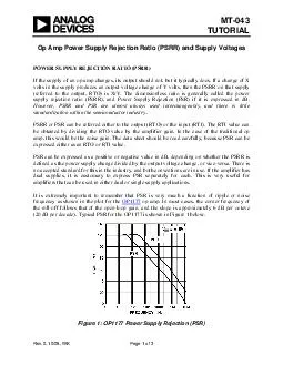
If a change of X volts in the supply produces an output voltage ch ange of Y volts then the PSRR on that supply referred to the output RTO is XY The dime nsionless ratio is generally called the power supply rejection ratio PSRR and Power Supply Reje ID: 26585

change

Share:

Link:

Embed:

Download Presentation from below link

Download Pdf The PPT/PDF document "MT TUTORIAL Op Amp Power Supply Rejectio..." is the property of its rightful owner. Permission is granted to download and print the materials on this web site for personal, non-commercial use only, and to display it on your personal computer provided you do not modify the materials and that you retain all copyright notices contained in the materials. By downloading content from our website, you accept the terms of this agreement.


Presentation Transcript

Op Amp Power Supply Rejection Ratio (PSRR) and Supply Voltages POWER SUPPLY REJECTION RATIO (PSRR) If the supply of an op amp changes, its output should not, but it ty(referred to the output, RTO) is X/Y. The dime op amp. In most cases, the corner frequency of nd the slope is approximately 6 dB per octave (20 dB per decade). Typical PSR for the OP1177 is shown in Figure 1 below. SS Rev.0, 10/08, WK MT-043 A test setup used to measure PSRR is shown in Figure 2 below. Note that it is similar to the test setup used to measure CMRR (see ). DUTOUT +- A1 10020k10k10k15V14V+15VPSRR (RTI) = 101 OUT A1: HIGH GAIN,LOW V, LOW I Figure 2: Test Setup for Measuring Pommetrical power supply change of 1 V. Other values may be used where appropriate, and the measurement can be made for the positive and negative supply POWER SUPPLIES AND POWER DISSIPATION Op amps have no ground terminal. Specifications for the power supply are quite often in the form ±X volts, but in fact it might equally be expressed as 2X volts. What is important is where the CM and output ranges lie relative to the supplies. This information may be provided in Often data sheets will advise that an op amp will work over a range of supplies (from +3 V to ±16.5 V for example), and will then give parameters at several values of supply, so that users may extrapolate. If the minimum supply voltage is quite high, it is usually because the device Data sheets also give current consumption. Any current flowing into one supply pin will flow out terminal. When the output is open circuit, the dissipation is easily calculated from the supply voltage and current. When current flows into a load, it is easiest emember that if the locurrent flows from a supply to ground, not betwdissipation. Data sheets normallyresistances and maximum junction temperature ratings, from which dissipation limits may be Page 2 of 3 r considerations relatinPOWER SUPPLIES AND DECOUPLING Because op amp PSRR is frequency dependent, op amp power supplies must be well decoupled. At low frequencies, several devices may share a 10-50 µF capacitor on each supply, provided it is no more than 10 cm (PC track distance) from any of them. +– C1C2++C3C4+VS–VS LARGE AREAGROUND PLANELEAD LENGTHMINIMUMC1, C2:LOCALIZED HFDECOUPLING,LOW INDUCTANCECERAMIC, 0.1µFC3, C4:SHARED LFDECOUPLING,ELECTROLYTIC,10 TO 50µF0cm0cm ‘‘(or so) capacitor with short leads/PC tracks. These capacitors must also provide a return path for hown in Figure 3 above. Further bypassing and decoupling information can be found in the last chapter of References 1 and 2.REFERENCES: Hank Zumbahlen, Basic Linear Design, Analog Devices, 2006, ISBN: 0-915550-28-1. Also available as Linear Circuit Design Handbook , Elsevier-Newnes, 2008, ISBN-10: 0750687037, ISBN-13: 978-0750687034. Chapter 1 Walter G. Jung, Op Amp Applications Analog Devices, 2002, ISBN 0-916550-26-5, Also available as Amp Applications Handbook , Elsevier/Newnes, 2005, ISBN 0-7506-7844-5. Chapter 1. Copyright 2009, Analog Devices, Inc. All rights reserved. Analog Devices assumes no responsibility for customer product design or the use or application of customers’ products or for any infringements of patents or rights of others which may result from Analog Devices assistance. All trademarks and logos are property of their respective holders. Information furnished by Analog Devices applications and development tools engineers is believed to be accurate and reliable, however no responsibility is assumed by Analog Devices regarding technical accuracy and topicality of the content provided in Analog Devices Tutorials. Page 3 of 3