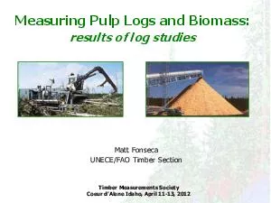
/
Seismic Design of Hillside Light Timber Frame Buildings Seismic Design of Hillside Light Timber Frame Buildings

Seismic Design of Hillside Light Timber Frame Buildings - PDF document

marina-yarberry
marina-yarberry . @marina-yarberry
Follow
401 views
Uploaded On 2015-08-07

Seismic Design of Hillside Light Timber Frame Buildings - PPT Presentation

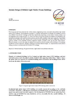
A Liu BRANZ New Zealand SUMMARY The study reported here examined the critical seismic engineering issues associated with hillside l ight timber frame LT F buildings The examination r ID: 102014

Liu BRANZ New Zealand SUMMARY :

Share:

Link:

Embed:

Download Presentation from below link

Download Pdf The PPT/PDF document "Seismic Design of Hillside Light Timber ..." is the property of its rightful owner. Permission is granted to download and print the materials on this web site for personal, non-commercial use only, and to display it on your personal computer provided you do not modify the materials and that you retain all copyright notices contained in the materials. By downloading content from our website, you accept the terms of this agreement.


Presentation Transcript

Seismic Design of Hillside Light Timber Frame Buildings A. Liu BRANZ, New Zealand SUMMARY : The study reported here examined the critical seismic engineering issues associated with hillside l ight timber frame (LT F ) buildings . The examination revealed: (1). Seismic characteristics of hillside LTF buildings coul d be very different from similar buildings on flat sites , significantly depending on the subfloor framing systems and the diaphragm action at ground level . (2). Due to the nat ure of the slope ground, the stiffness incompatibility will inevitably be present in the subfloor frame systems and the stiff er systems would resist majority of the lateral seismic actions before the softer systems start to resist the load , depending on the floor diaphragm. Hence t h e subfloor systems could potentially develop progressive failure (collapse) under up - and - down slope seismic . When the seismic is across the slope, t he superstructure and the subfloor systems of the buildings could undergo signi ficant torsional responses , leading to premature structural failure/collapse. (3). Displacement - based seismic design procedure is recommended for hillside LTF buildings. Keywords: Hillside building s , Progressive failure, Light timber frame, Seismic beha viour 1. INTRODUCTION Majority of residential buildings in New Zealand are light timber frame (LTF) buildings and their structural systems can be described as timber sheathed walls supporting timber floors. Figure 1 shows the timber sticks in a typical LTF residential building under construction and sheathing boards will be fixed onto the timber sticks afterwards. Figure 1 A t ypical l ight t imber f rame (LTF) building under construction Residential light timber frame (LTF) buildings are usually constructed according to the cookbook “NZS3604” (SNZ2011) . Although the construction of residential houses to NZS3604 does not require inputs from professional structural engineers, the development of NZS3604 has an engineering basis and the scope of NZS3604 has many limitations, suc h as, reasonably flat sites, regular buildings, 10 m eters in total height, etc. More and more residential buildings in New Zealand are built on hillside sites nowadays because flat land is becoming more scarce due to New Zealand’s unique geographical feat ures and also people love the spectacular views from hillside sites. While many of the structural design issues of hillside light timber frame residential buildings are similar to light timber frame residential buildings within the scope of NZS3604, their seismic bracing performance could be very different from that within the scope of NZS3604. Figure 2 shows comparison of typical LTF buildings on hillside and LTF buildings within the scope of NZS3604. Apparently, in comparison with LTF buildings withi n the scope of NZS3604, hillside LTF residential buildings are characterised by (1) t he main part s of hillside LTF buildings being constructed in similar way to the superstructures of LTF buildings within NZS3604; (2) m ain difference between hillside LTF b uildings and buildings within NZS3604 being the subfloor construction; (3) s tiffness incompatibility always present in the subfloor frames due to the nature of slopping ground and/or mixture of subfloor systems; (4) v iolation of regularity (vertical regula rity and/or plane regularity) due to the irregularity in subfloor systems; and (5) p otentially different founding levels for hillside LTF buildings. As a result, seismic design philosophy of hillside LTF buildings could be different from those within NZS 3604’s scope. Figure 2 Comparisons of LTF b uildings on h illside and LTF b uildings within NZS3604 There is no guidance available for seismic design of hillside light timber frame houses in New Zealand. Therefore, seismic design methods used can vary significantly from design to design, creating greater difficulties for the design engineers to demonstra te the design compliance to the building consent authority (BCA) people, meanwhile the BCA people have no guideline s to use to establish the compliance of a structural design with the building code. The paper presented here is to identify the critical se ismic design issues associated with LTF buildings on hillsides and develop a rational seismic design philosophy for hillside LTF buildings. 2. DESIGN PHILOSOPHY OF NZS3604 Structural systems of light timber frame (LTF) residential buildings in New Zealand are timber floors supported by timber sheathed walls constructed of closely spaced timber studs and sheet linings. Design standard for light timber frame buildings in New Zealand is commonly NZS 3604 and a pplication of NZS3604 has limitations (Shel ton 2007) . If the proposed buildings are within the scope of NZS3604, the building construction do es not require specific structural engineering design . The limits set out in NZS3604 include the building size, height and roof slope, floor loadings, and snow loadings. In NZS3604, w ind and earthquake loads are also limited by restricting the zone or area in which LTF buildings may be situated. For buildings or elements of buildings outside the se limits, a specific structural design is required. Unlike other engineered steel or reinforced concrete building structures which have widely spaced stronger load resisting elements, LTF residential buildings constructed to NZS3604 are characterised A typical down - slope LTF building A typical LTF building to NZS3604 A typical up - slope LTF building by having numerous, closely spaced resisting elements. As a result, LTF buildings within the scope of NZS3604 are relatively stiff and likely to have lots of redundancy. In a major earthquake, the buildings in this category perform in a way similar to wall s tructures, so the failure mechanism is likely to be a ductile failure mode. For seismic design of LTF buildings, the earthquake load resisting demand in NZS3604 was derived following essentially the “Equivalent Static Method”, a force - based approach, bec ause LTF buildings within the scope of NZS3604 meet the requirement criteria for using equivalent static method specified by NZS 1170.5, (SNZ 2004 ), which are either the building structure being regular, or the fundamental period being less than 0.4 s or t he building height being less than 10 m. NZS3604 has assumed that the ductility factor, µ, in estimating seismic action coefficient associated with equivalent static method is 3.5 because a reasonable ductile failure mode is expected. It is recommended by NZS3604 that the ductility factor of 3.5 be used where equivalent specific designs are being undertaken for timber framed buildings outside the scope of NZS 3604. 3. CONSTRUCTION CHAR ACTERISTICS AND SEIS MIC BEHAVIOUR OF HIL LSIDE LTF BUILDINGS Seismic responses of building structures are affected by many building characteristics, such as, building configuration s, building’s dynamic properties, and interaction of the foundation structural (subfloor system) system with the superstructures, so on. For exam ple, an irregular structural system can develop significant stress concentration, deformation concentration or torsional responses in earthquakes and this is a typical example showing the effect of building layout on the seismic response of buildings. Rega rding the interaction of the foundation structural (subfloor system) system with the superstructures, a base - isolated building fits into this category . Base - isolation technique can significantly modify the interaction of the foundation structural (subfloor system) system with the superstructures , and consequently significant ly modif ying building’s seismic characteristics, such as, dynamic property, energy dissipating mode, and so on. Major difference between hillside LTF buildings and the buildings constr ucted to NZS3604 is the subfloor systems. Consequently hillside LTF buildings have different building configuration layout and different interaction between the foundation structural (subfloor system) system and the superstructures, in comparison with LTF buildings within the scope of NZS3604. The subfloor frame systems of hillside houses are the systems between moving ground and the superstructure, their responses to the moving ground and the interactions with the superstructures are different from similar buildings founded on flat sites, leading to very different seismic response, in comparison with the buildings within the scope of NZS3604. Figure 3 Upper s lope b uilding s versus d own - s lope b uilding s Construction techniques of subfloor frame systems of hillside LTF buildings vary a lot, depending on the relative locations of the buildings to the street access. This has caused significantly varying seismic performance of different hillside LTF buildings . Hillside LTF buildings can be generally divided into two broad categories: up - slope buildings and down - slope buildings as s hown in Figure 3. Construction characteristics of these two categorised LTF buildings are very different from each other and they a re also different from th ose within the scope of NZS3604. Consequently seismic performance of up - slope LTF buildings could be very different from that of down - slope buildings and seismic performance of hillside LTF buildings could be very different from th at of NZS3604. This is to be examined as follows in this section. 3.1. Up - s lope LTF r esidential b uildings As shown in Figure 3, up - slope LTF buildings are the buildings on the ground that rises above their street. Up - slope LTF buildings are often buil t into the ground because their design tries to incorporate site features to minimize the street access and construction problems posed by the land rising above the street. As a result, the up - slope LTF buildings are basically founded directly on or relati vely close to its foundations on ground. Figure 4 shows a typical up - slope house construction. Figure 4 A t ypical u p - s lope h ouse Regarding dynamic properties, up - slope LTF buildings generally are at least as stiff as similar buildings within NZS3604 scope, as shown in Figure 5 and are likely to have a fundamental period less than 0.4 second. Therefore the seismic actions for up - slop e LTF buidlings can be determined using equivalent static method, according to AS/NZS1170.5. LTF House Designed to NZS3604 UP - Slope LTF House T 1 ≤ 0.4 s T 1 ≤ 0.4 s Can use equivalent static method Can use equivalent static method Ductile failure mode Ductile failure mode Ductility assumed = 3.5 Ductility capacity is similar to 3.5 Figure 5 Comparison with buildings to NZS3604 Under lateral seismic actions, deformation profile of up - slope LTF buildings along the building height is similar to that of buildings within the scope of NZS3604 but the overall deformation is likely to be less than that within the scope of NZS3604. LTF building structures in this category are believed to have similar resilience in earthqu a kes to bu ildings within scope of NZS3604, hence similar ductility and similar damping capacity can be assumed. In a word, up - slope LTF buildings built into ground are expected to perform in a similar way to that of buildings within scope of NZS3604. It has to b e appreciated that retaining walls on the uphill need special considerations. Typically retaining walls on uphills provide supports to the main building and also provide lateral retaining for the soil. Hence the re t aining walls need to have adequate out - o f - plane resistance for combined actions of lateral soil actions and seismic actions associated with the allocated building weight when subjected to up - and - down slope seismic action. 3. 2 . Down - s lope LTF r esidential b uildings Down - slope LTF residential buildings are built on ground that drops below the street. It is common that down - slope LTF buildings are founded on substantial subfloor framing systems because their design intends to minimize access and construction problems p osed by the land dropping away from the street. As a result, down - slope buildings have the main buildings generally separated from its foundations by a substantial supporting structure (subfloor framing structures). Figure 6 shows a typic al down - slope hous e . Apart from the fact that the subfloor framing structure is substantial for down - slope buildings as stated above, their subfloor frames are often a mixture of different systems, such as, a mixture of braced pile bents, sheathed timber walls, RC or block foundation walls, so on. Different subfloor frame systems have different stiffness/dynamic properties; therefore seismic response of subfloor framing systems in this category often has severe stiffness incompatibility problem, which is a critical seismic issue associated with mixed structural systems. Due to the nature of slopping ground, stiffness incompatibility in subfloor system will exist even the subfloor system consists of identical structural systems, when the seismic is in up - and - down slope direc tion. As shown in Figure 7, the subfloor frames of a down - slope building are braced pile bents and the two pile bents, A and B, are likely to have different stiffness due to the height differe n ce. This phenomenon is similar to bridge piers when the bridge is subjected to longitudinal earthquakes. Consequence is potential progressive failure, stress concentration and deformation incompatibility issues. Under the same amount of displacement at the floor level, different parts of the braced pile bents in Fugu re 7 could be stressed very differently. Stiffer system, bent “B”, resists more action than bent “A” until it fails. Subsequently the total seismic actions are redistributed to bent “B”, potentially leading to failure of bent “B”. If there are more than tw o later a l load resisting systems, the progressive failure will occur to the stiffest system first, then to the next stiffest system, potentially leading to the progressive failure of the entire subfloor systems. Such a failure mechanism in subfloor systems is undesirable and special considerations have to be taken to prevent it from happening. Apart from the above stated progressive failure in subfloor systems associated with stiffness incompatibility of subfloor frame systems, down - slope LTF residential buildings could have very differen dynamic response in comparison with LTF buildings within the scope of NZS3604. It is common that the subfloor frames contains only braced piles for down - slope houses and Figure 8 shows an indicative section of a down - slop e LTF buidling on braced piles. Braced piles are likely to be much more flexible than the superstructure which is of timber sheathed wall construction (Thurston 1993) . As a consequence, the building fundamental period is likely to be longer than 0.4s. Acco rding to NZS1170.5, the building seismic design actions can no longer be determined by using equivalent static method. In addition, the overall deformation profile of the buidling in earthquakes is similar to that of a soft storey building as shown in Figu re 8, which is an undesirable mechanism. Hence the recommended ductility capacity of 3.5 in NZS3604 may be invalid because of undesirable failure manner. Figure 6 One Typical Down - Slope House with Figure 7 Progressive Failure in Subfloor Systems, Substantial Subfloor Frames Subjected to Down - the - Slope Seismic Figure 8 Down - Slope LTF House on Braced Poles Another critical aspect associated with down - slope LTF buildings is the potential torsional response when the seismic action is in across - the - slope direction as shown in Figure 9. Under across - the - slope seismic, the subfloor frames are likely to have signi ficantly different stiffness from bracging grid to bracing grid. Typically the outmost external subfloor frame at lowest ground point of the building will be very flexible and the inner most subfloor frame, which is probably the foundation beam or retainin g wall at uphill, is very stiff. Assume that the inner most brace line has the foundation beam s/ walls , the main floors will behave like a cantilever deep beam rotating about the foundation beam/wall at uphill because the outmost subfloor frame is very fle xible , leading to significant torsional response. In this case, very big reactions will be generated in the end connections from the building to the uphill foundation beams, potentially leading to the progressive failure of the connections and eventually t he collapse of the building. If the innermost braced line is the retaining wall, the retaining walls will be subjected to a significant torsional action, jeopardising the retaining wall performance if the wall is not designed for it. In addition, significa nt torsional response in the superstructure could cause much larger deformation to some parts of the superstructures and also possibly amplify the stresses in some areas of the main structural elements including diaphragms and the load resisting subfloor s ystems. In this case, diaphragm’s flexibility could be critical in distributing the loads to different systems and should be considered in the structural analysis. For residential buildings, the floor diaphragms are of timber construction, adequacy of timb er floor disphragms in transferring the seism i c a ctions across the building ha s to be investigated. Figure 9 Deformation of the Main Floor When Subjected to Across - the - Slope Seismic 3. 3 . Summary In summary, hillside LTF buildings can be categorised as two broad categories: up - slope buildings and down - slope buildings and seismic performance of hillside LTF buildings is largely dependnent on the engineering characteristics of the subfloor frames. The theoretical exmaination reveals the foll owing findings: Up - slope LTF buildings are often founded immediately onto or close to ground and their seism ic performance is expected to be similar to that of the buidlings within NZS3604, in terms of deformation profile, dynamic properties and energy d isspiating capacity. However s eismic performance of down - slope LTF buildings could potentially be very different from that of the buidlings within NZS3604, because substantial subfloor frames potentially can result in significant modification of seismic p erformance of down - slope LTF buidlings. When the seismic is in up - and - down the slope direction, critical seismic issues include stiffness incompatibility in subfloor frames , undesirable soft storey failure mechanism and potential progressive failure in su bfloor systems so on. When the seismic is in across - the - slope direction, significant torsional response could occur, potentially causing significant distorion of the structural performance and increa s ing the de m and for floor diaphragm to t r an s fer the seismic actions across the entire building . 4. RATIONAL SEISMIC DESIGN PROCEDURES OF HILLSIDE LTF BUILDINGS Seismis resistance of a building structure is the combination of strength capacity and deformation capacity. Based on the findings revealed from the above examination, rational seismic design for hillside LTF buildings is proposed a nd presented here. 4.1 . Up - slope LTF r esidential b uildings For up - slope LTF houses, the seismic design actions can be derived based on the same principles as used by NZS3604 as far as the superstructure construction meet the limits specified by NZS3604. In detail, equivalent static method can be used in deriving s eismic actions and the overall structural ductility of 3.5 can be assumed. Special consideration needs to be given to uphill retaining walls in order to achieve the overall structural stability. Uphill walls need to be adequately designed for combined out - of - plane actions resulting from seismic action s assictaed with building weight in up - and - down slope direction and the lateral actions from the soils behind the walls. 4.2 . Down - slope LTF r esidential b uildings Unlike up - slope LTF buildings, variatio ns of seismic response charactereitics of down - slope LTF buidlings, such as, expected failure mechanism, the dynamic properties and the deformation profile, from th o se of the buidlings within NZS3604 have to be taken into account. Seismic design principles used by NZS3604 are no longer appropriate for seismic design of down - slope LTF buildings. Rational seismic design has to consider (1) progressive failure/collapse in subfloor systems when the seismic is in up - and - down the slope direction, and (2) the effe cts of significant torsion al response when the seismic is in across - the - slope direction. To prevent potential progressive failure in subfloor frames in up - and - down the slope seismic event, it is suggested to use displacement - based approach in deriving th e seismic actions of the subfloor systems. In detail, the subfloor frames are model l ed by linking them together by rigid links and the seismic resistance is obtained by subjecting the entire system to the same designated translational displacement, Δ cap , as shown in Figure 10 , where Δ cap is the displacement at mass center and is determiend based on desired performance requirements . Floor diaphragm stiffness needs to be allowed for in order to assess the effect on the load distribution to different systems. If necessary, load distribution s to differnet systems need to be adjusted. The seismic resistance , R, of the entire subfloor system is the summation of the force capacities of all the subfloor systems at the designated displacement, ∆ cap . The combination of R and ∆ cap will give the reliable seismic capacity. Effective period, T eff , can then be found based on R and ∆ cap and it will be used to derive the seismic actions for the LTF superstructure. For seismic design of the LTF superstructure, ductility capac ity of the superstructure can be assumed as limited and it is suggested to be µ = 2 because of the unfavourable failure mode in subfloors. Figure 10 Modelling of the Subfloor System s Regarding the resolution of the significant torsion when subjected to across - the - slope seismic, the ground floor diaphragm needs to be designed adequately to activate the torsional resistance by the subfloor systems perpendicular to the seismic direction. In addition, there should be sufficient number of evenly spaced latera l load resisting systems in across the slope direction. 5 . CONCLUSIONS Study reported here is on seismic design of hillside LTF buildings where the main buildings are generally within limits set by NZS3604 but on a hillside site . Examination of seismic engineering characteristics of hillside LTF buildings led to the following conclusions: 1. Main difference between hillside LTF buildings and buildings constructed to NZDS3604 is the subfloor structure between ground and the main building. Different constructions of the subfloor systems for hillside LTF building s can alter the seismic behaviour of hillside LTF buildings in many aspects. Hillside LTF buildings have two broad categori es, up - slope buildings and down - slope buildings. Up - slope buildings are founded immediately on ground, similar to the buildings within the scope of NZS3604. In contrary, down - slope LTF buildings have the main buildings separated from the ground by a substa ntial subfloor structure. 2. Seismic characteristics of up - slope LTF buildings are expected to be similar to these within the scope of NZS3604. In detail, the fundamental dynamic period, deformation profile along the building height and failure mechanism of up - slope LTF buildings are similar to these of LTF buildings to NZS3604. However the retaining walls on up hill needs special consideration to ensure the adequate out - of - plane capacity to resist the combinaed actions from the lateral soil pressure and the seismic action associated with the allocated building weight. Unlike up - slope LTF building, s eismic characteristics of down - slope LTF buildings are expected to be very different from th ese buildings within the scope of NZS3604 due to irregularity in the subfloor frames. Under up - and - down slope seismic, undesirable progressive failure mechanism could occur in subfloor frames due to stiffness incompatibility in subfloor frames. As a result, the available ductility capacity could be less than assumed by NZS3604 . Fundamental period of the building could be longer than that assumed by NZS3604 , which is 0.4 s , so equivalent static method is no longer appropriate. Under across - the - slope seismic, significant torsion could occur due to stiffness irregularities in subfloor frames. In this case, adequacy of the timber floor diaphragm at ground level has to be considered in order that induced torsional actions can be resolved effectively. 3. Regarding seismic design of hillside LTF buildings, up - slope buildings can use the same principles as in NZS3604 and design actions can be derived based on equivalent static method and a displacement ductility of 3.5. However seismic design of down - slope LTF buildings need a different design approach from NZS3604 and will requir e special structural engineering design. It is suggested that the direct displacement - based procedure be used in deriving the seismic actions. The effective period of the entire building system used in deriving seismic actions is found by modelling the mai n building (the superstructure) as rigid and subjecting all the subfloor frames to same magnitude of displacement at floor level. In estimating the seismic demand for the main buildings, a displacement ductility of 2 is tentatively suggested because, altho ugh the failure mechanism in subfloor frames is undesirable, the main building has got sound structural resilience. To have adequate torsional resistance for down - slope buildings under across - the - slope seismic, floor diaphragm needs to be adequately desi gned to activate the lateral load resisting systems perpendicular to the seismic direction. ACKNOWLEDGEMENT The valuable discussions and advices provided by other structural engineers at BRANZ, especially by Roger Shelton, are gratefully acknowledged. REFERENCES Liu, A. (2011). Guidance for Bracing Design of Hillside Houses, Building Research Association of New Zealand. Study Report SR262 Shelton, R.H. (2007). The Engineering Basis of NZS3604, Building Research Association of New Zealand. Study Report SR168 Priestley, N.J., Calvi, G.M. and Kowalsky, M.J. (2007). Displacement - based Seismic Design of Structures, IUSS Press, Pavia, Italy Standard New Zealand ( 1993 ). NZS 3603:1993 Timber Structures Standard Standard New Zealand ( 2004 ). AS/NZS 1170.5 :2004. Structural Design Actions Part 5: Earthquake Actions - New Zealand Standard New Zealand ( 20 11). NZS 3604:2011. Timber Framed Buildings Thurston, S. J. ( 1993 ) . Design Strength of Various Foundation Systems. Building Research Association of New Zealand, Stud y Report SR46