/
TS Interim Amendment N 25 Assessment and Upgrading of Existing TS IA 2 TS Interim Amendment N 25 Assessment and Upgrading of Existing TS IA 2

TS Interim Amendment N 25 Assessment and Upgrading of Existing TS IA 2 - PDF document

marina-yarberry
marina-yarberry . @marina-yarberry
Follow
481 views
Uploaded On 2015-09-20

TS Interim Amendment N 25 Assessment and Upgrading of Existing TS IA 2 - PPT Presentation

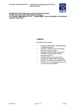
TRANSPORT SCOTLAND Agency of the Scottish Executive TRUNK ROAD NETWORK MANAGEMENT Bridges TS INTERIM AMENDMENT No 25 ID: 134703

TRANSPORT SCOTLAND (Agency the

Share:

Link:

Embed:

Download Presentation from below link

Download Pdf The PPT/PDF document "TS Interim Amendment N 25 Assessment and..." is the property of its rightful owner. Permission is granted to download and print the materials on this web site for personal, non-commercial use only, and to display it on your personal computer provided you do not modify the materials and that you retain all copyright notices contained in the materials. By downloading content from our website, you accept the terms of this agreement.


Presentation Transcript

TS Interim Amendment N 25 Assessment and Upgrading of Existing TS IA 25.doc Page 1 of 44 Aug07 TRANSPORT SCOTLAND (Agency of the Scottish Executive) TRUNK ROAD NETWORK MANAGEMENT (Bridges) TS INTERIM AMENDMENT No 25 – ASSESSMENT AND UPGRADING OF EXISTING VEHICLE PARAPETS SUMMARY This Interim Amendment: Supersedes BA 37/92, “Priority Ranking Introduces ALARP based risk ranking tools for existing parapets Supplements and partially supersedes TD 19/06, “Requirement for Road Restraint Systems” Provides advice on assessment of parapet and safety barrier supporting members on bridges and retaining walls Provides advice on substandard parapet connections and transitions TS Interim Amendment N 25 Assessment and Upgrading of Existing TS IA 25.doc Page 2 of 44 Aug07 TRANSPORT SCOTLAND INTERIM AMENDMENT No. 25 ASSESSMENT AND UPGRADING OF EXISTING VEHICLE PARAPETS CONTENTS Section Description Page No. Introduction...................................................................................................3Scope............................................................................................................3Implementation.............................................................................................4ALARP Based Risk Assessment Framework...............................................4Risk Assessment of Existing Parapet Sites..................................................5Assessment of Parapet Remnant Containment Capacity.............................9Upgrading of Existing Parapets..................................................................12Obsolete/Substandard Parapet Connections and Transitions....................15List of Documents to be Withdrawn/Amended............................................18References.................................................................................................18ALARP Based Risk Ranking Tools.............................................................20Incursion Risk Ranking Tools.....................................................................24Identification of Substandard BACO Parapets............................................42Assessment of Parapet Supporting Members............................................43 TS Interim Amendment N 25 Assessment and Upgrading of Existing TS IA 25.doc Page 4 of 44 Aug07 3. Implementation This TS IA should be used on all schemes, except for those already under construction or those currently being prepared where there would be significant additional cost or delay caused by its use. Refer to TD 19/06 clauses 1.41 to 1.44 for the terminology, definitions and 4. ALARP Based Risk Assessment Framework The risk assessment approach adopted in this TS IA is consistent with the risk-theory based approach adopted in TD 19/06. TD 19/06 and this TS IA adopt the ALARP principle in assessing tolerability of risk levels. ALARP (As Low as Reasonably Practicable) originated in the nuclear industry as a method for ranking and prioritising responses to risks. The Health and Safety at Work etc Act 1974 recognises the ALARP principle in addressing risk. There is a level of risk considered “intolerable” to individuals and society, and similarly a level of risk considered “broadly acceptable”. If the risk falls in the “tolerable region” between these two levels, then the Act requires that the risk be reduced to a level which is “as low as reasonably practicable” provided that the cost or effort required to reduce the risk is not grossly disproportionate to the benefits (the ALARP principle). The principle is illustrated diagrammatically in Fig. 2.1 of TD 19/06, reproduced here as Fig. 4.1. Existing parapets assessed to be within the “broadly-acceptable region”, or those which satisfy the ALARP principle, are considered acceptable and do not require upgrading. Where parapets are upgraded, the risk should either be reduced to “broadly-acceptable”, or satisfy the ALARP principle. In both these cases, departures from standards are not required. (Partially supersedes clauses 1.40 and 4.10 of TD 19/06) Use of the ALARP based risk ranking tools (given in Appendix A) and incursion risk ranking tools (given in Appendix B) ensure that the risks associated with existing parapet sites are managed in accordance with the ALARP principle, utilising the RRRAP only where the risks associated with existing parapets cannot be demonstrated to be “as low as TS Interim Amendment N 25 Assessment and Upgrading of Existing TS IA 25.doc Page 5 of 44 Aug07 reasonably practicable”. This approach also enables relative risk levels to be established, together with suitable mitigation measures, as shown in Table 4.1. (Partially supersedes clauses 4.9 and 4.10 of TD 19/06) Where use of the RRRAP identifies the need for a higher level of containment than N2 on an existing structure, it is essential for the cost-related default values to be overwritten, to reflect the fact that the additional costs associated with providing a higher level of containment are usually far more than they would be for a new structure. Moreover, where the RRRAP identifies the need for Very High Containment Level (H4a) on an existing site, this must only be provided after consultation with the responsible authorities and subject to prior approval of the Technical Approval Authority. (Partially supersedes clauses 2.34 and Table 4.1 Risk Levels, ALARP and Risk Mitigation Risk Level Relative Risk (ALARP) Risk Mitigation High ALARP requires H4a upgrade Upgrade to H4a Medium ALARP requires H1/H2 upgrade Upgrade to H1/H2 Low ALARP requires N1/N2 upgrade Upgrade to N1/N2 Very Low Existing parapet is ALARP Monitor Risk Negligible Existing risk is “broadly acceptable” Do Nothing Notes: 1. Existing parapets with remnant capacities less than the required pedestrian level of containment should be considered as high risk, requiring upgrading to appropriate containment levels determined by ALARP. 2. N1 or N2 dependent on TD 19/06 minimum design containment requirements. 3. No mitigation is required but the risk should be monitored against ALARP. Where schemes are “notifiable” under the CDM regulations, the results of ALARP based risk assessments carried out in the design of parapet upgrading works should be included as part of the Health and Safety documentation required under the CDM Regulations. For tendered schemes this will be prior to invitation to tender; for Design and Build (D&B) or Design Build Finance Operate (DBFO) schemes, prior to commencement of construction; and for term maintenance and framework contracts, prior to issue of the Order sedes clauses 1.25 and 1.29 of TD 19/06) 5. Risk Assessment of Existing Parapet Sites The ALARP based risk assessment process is illustrated by the flowcharts in figures 5.1 and 5.2 for bridges over roads and bridges over railways respectively. Note that the road-over-road incursion tools do not apply when the two-way AADT on the upper or lower road is less than 25000. The flowcharts should also be used for retaining walls supporting roads. However, the incursion risk ranking tools only apply when it is considered possible for a parapet penetrating vehicle (or associated debris) to foul the lower route (railway or road). In these exceptional circumstances, the incursion risk ranking tools for bridges given in Appendix B should be used. TS Interim Amendment N 25 Assessment and Upgrading of Existing Vehicle Parapets TS IA 25 Page 7 of 44 Aug 07 100 COMPILE DATA ALARP� 1.0 CONT CMIN CALL Undertake RRRAP/of Upgrading Options N1/N2 Upgrade H4a Upgrade H1/H2 Upgrade Monitor Only N1/N2 Upgrade No Work Required Stand-Alone Schemes Undertake as Part of Major Maintenance Works V. LOW RISK MEDIUM RISK HIGH RISK LOW RISKH4a RequiredH1/H2 RequiredN1/N2 RequiredFigure 5.1 Assessment Flowchart — Bridges over Roads Note: For bridges over roads, RINC should be considered to be less than 100 when the two-way AADT on either the upper or lower road is less than 25000. TS Interim Amendment N 25 Assessment and Upgrading of Existing TS IA 25 Page 9 of 44 Aug 07 6. Assessment of Parapet Remnant Containment Capacity Parapets may be classified fundamentally into those which were built before the advent of design criteria based on containment in 1967, and those which have been built since that date. Most pre-1967 parapets have since been replaced or protected. Pre-1967 parapets include a large number of masonry and brick parapets, generally associated with masonry arch bridges. These rely principally on their mass to keep the stresses in the mortar layers compressive under light to moderate impact loadings. They cannot be relied on to contain heavier vehicles travelling at speed, and secondary incidents may be initiated by falling debris. Many masonry parapets have been upgraded by providing a reinforced concrete stem which may have been integral with a horizontal slab spanning all or part of the way transversely across the bridge. Such reinforced concrete parapets may have been clad with masonry or brick slips to retain their original appearance. Where masonry and brick parapets have been provided on older types of bridges other than masonry arch structures, the problems of upgrading have been similar to those described in Pre-1967 bridges, other than arches, often had a variety of parapet types, including wrought iron, cast iron, steel, timber, masonry, in situ and precast concrete. The superstructures of these bridges may not have sufficient capacity to transmit the impact forces from parapets of modern containment standards, and, unlike arch bridges, may not have sufficient reserves of dead load capacity to allow additional strengthening members to be added to the structure. Consequently, upgrading has often comprised provision of protective safety barriers, or, more rarely, modifications to the structure. Parapets built since 1967 (or earlier parapets known to be designed to BE5) were designed to standards which may be considered as broadly equivalent to current standards in terms of containment characteristics. Such parapets should be considered as acceptable unless there are known faults, as listed below: parapets demonstrated to be incorrectly designed or constructed, e.g., some early parapets were detailed without proper continuity in the longitudinal members; parapets designed to lower containment criteria than would be required by current parapets which have exhibited significant deterioration; this includes steel members which have corroded and parapet fixings, to the extent that there has been a significant loss of design capacity; parapets with other known material problems, including embrittlement in certain parapets which have been damaged and have not been satisfactorily repaired, where there would be significant loss of design capacity. Evaluation of Remnant Containment Capacity The containment capacity of existing masonry parapets should be assessed in accordance with BS 6779-4. The strength of pre-1967 parapets should generally be assessed on the basis of engineering judgement. To help in this process, it may be appropriate to carry out occasional strength checks based principally on the resistance of the existing parapet. In this regard TS Interim Amendment N 25 Assessment and Upgrading of Existing TS IA 25 Page 11 of 44 Aug 07 Where protective safety barriers are provided with working widths less than required by TD 19/06 or the NPSBS (Rev. 1), they should be considered as substandard. Where the speed limit is less than 50mph, or the two-way traffic flow is less than 7000, the risk should generally be considered to be negligible. Outside these limits, risks should be assessed using the ALARP based risk assessment tool for substandard protective safety barriers included in Appendix A. Any upgrading work justified should be carried out as part of major maintenance, or as part of a TPI. The assessment and upgrading of obsolete/substandard parapet connections and transitions is covered in section 8. As-built post-1967 steel N2 and N1 parapets may be assumed to have effective containments of 1.50•N2 and 0.75•N2 respectively, except for N1 vertical rod infill parapets where an effective containment of 0.33•N2 should be assumed. Assessed capacities should reduce as-built values when there is significant deterioration or defects. As-built steel normal containment parapets may be considered as roughly equivalent to H1/H2 containment, with regard to the potential to prevent incursion. Where the loss of condition of such parapets does not reduce the containment capacity by more than 20% from the as-built value, H1/H2 containment may be assumed when a RRRAP or similar risk assessment is undertaken. As-built post-1967 Aluminium N2 and N1 equivalent parapets may generally be assumed to have effective containments of 1.00•N2 and 0.50•N2 respectively. Assessed capacities should reduce as-built values when there is significant deterioration or defects. As-built substandard BACO N2 and N1 equivalent parapets may be assumed to have effective containments of 0.50•N2 and 0.25•N2 respectively. Assessed capacities should reduce as-built values when there is significant deterioration or defects. BACO parapets should be considered for assessment and upgrading as for other substandard parapets, based on the assumptions of remnant containment given in clause 6.18. Appendix D provides guidance on the identification of substandard BACO Parapets supplied by Lindley between 1994 and 1996 were inspected to identify whether the rails were from an unacceptable source (Hulett). Any rails identified as Hulett were to be replaced and details recorded. It is likely that all such defective rails have now been replaced. However, if it is suspected that Lindley parapets from this period still have defective rails, the TS UBMs should be consulted for advice. Assessment of Vehicle Parapets within Carriageway Widening/Realignment Schemes Where carriageway widening/realignment schemes allow the possibility of retaining existing parapets, the parapets should be assessed in relation to the proposed carriageway TS Interim Amendment N 25 Assessment and Upgrading of Existing TS IA 25 Page 13 of 44 Aug 07 Where existing parapets are to be upgraded, the required level of containment should be determined from the risk assessment process given in section 5, subject to the following minimum containment levels: N2 for any parapets on roads with speed limit of 50mph or more, or on any road over or adjacent to a railway. N1 for parapets on roads with speed limit of less than 50mph, other than on roads over or adjacent to railways The existing approach and departure safety barriers should also be upgraded, where necessary, to ensure compliance with TD 19/06 and the RRRAP. The containment level of the safety barrier should generally not exceed the required containment level of the parapet as determined by this TS IA. In particular, opportunity should be taken to ensure “length of In addition to the requirements of clause 7.4, for the following types of structures containment levels of new parapets should be no less than the as-built containment level of the existing parapets: Bridges over or retaining walls adjacent to railway lines. Bridges over or retaining walls adjacent to roads, where the two-way AADT values for Viaducts longer than 100m carrying roads with two-way AADT exceeding 25000. Where the existing parapets to these structures are steel N2 containment parapets, it is necessary to replace with a minimum containment level of N2 for steel parapets, or H1/H2 for The assessment and upgrading of obsolete/substandard parapet connections and transitions is covered in section 8. Parapet Supporting Members on Existing Bridges and Retaining Walls Before upgrading existing vehicle parapets, the parapet supporting member must be checked to ensure that there is adequate strength to resist vehicle collision loads. Refer to Appendix D for the loading requirements applicable to upgrading. Where parapet supporting members are unable to satisfy the vehicle collision load criteria given in Appendix D, the following additional options should be considered: Provide a continuous panel type safety barrier, near the edge of the deck or the face of the retaining wall, instead of a parapet. (Ref. clauses 7.12 and 7.13) Provide an additional protective safety barrier with appropriate setback and working width. (Ref. Clauses 7.11 to 7.13) Where the alternative options given in 7.8 prove impractical or disproportionately expensive a further option of allowing a partial reduction of the Appendix D loading requirements may be considered, subject to the submission of a departure from standards. The submission should demonstrate that the proposed solution satisfies the ALARP principle. (i.e., by demonstrating that the costs and effort involved in complying with clause 7.7 would be grossly disproportionate to the benefits) TS Interim Amendment N 25 Assessment and Upgrading of Existing TS IA 25 Page 15 of 44 Aug 07 Anchorage Systems for Parapets It is important to make use of existing anchors wherever possible, as this will tend to be significantly more cost-effective and less disruptive than installing new anchors. Where parapets are upgraded, existing drilled-in expanding anchors should be replaced by new cast-in cradle or drilled-in resin anchors that conform to current design standards, unless otherwise agreed by the Technical Approval Authority. It may be possible to re-use existing drilled-in resin anchors or cast-in cradle anchorages, subject to satisfactory proof load testing, and subject to the approval and recommendations of the parapet manufacturer for modifications to the base plates and holding down bolts arrangements which are normally required to fit the cradles. The modified components should normally be designed in accordance with BS 6779-1, subject to the agreement of the parapet manufacturer. Proof load testing of existing anchorages should be accordance with the provisions within the Specification for Highway Works. The number of anchors to be tested should be Where existing anchorages are unable to satisfy the proof loading criteria, it may be possible to consider a partial relaxation of the loading requirements given in clause 7.17 subject to the submission of a departure from standards. The submission should demonstrate that the proposed solution satisfies the ALARP principle. (i.e., by demonstrating that the costs and effort involved in complying with clause 7.17 would be grossly disproportionate to the benefit) and be supported by the parapet manufacturer. Guidance on the design of drilled-in anchorages for vehicle parapets is provided in clauses 4.63 to 4.69 of TD 19/06. 8. Obsolete/Substandard Parapet Connections and Transitions Background The following types of parapet to safety barrier connections are currently approved for use on Transport Scotland’s trunk road network: Transitions successfully tested to meet the requirements of EN 1317-4 and approved by Transport Scotland for use on its network. These systems are generally specific, in the sense that they enable connection from a particular parapet to a particular Transitions detailed in revision 1 of the “Non-Proprietary Safety Barrier Systems” (NPSBS Rev 1), which are deemed acceptable by Transport Scotland for use on its network, because they have proven in-service use over a number of years. In some cases they have been successfully tested. These systems are generally generic in nature, enabling connections from a variety of parapet types to the old non-Non-approved parapet connections, which nevertheless satisfy the design requirements of clause 6.5.1.4.1 of BS 6779-1, should be considered as acceptable for assessment purposes. To satisfy the BS 6779-1 requirements a connection must comprise one of the two alternative options: TS Interim Amendment N 25 Assessment and Upgrading of Existing TS IA 25 Page 17 of 44 Aug 07 Where there is no connection between a parapet and safety barrier with a full height anchorage adjacent to the parapet end post, this arrangement should be considered as acceptable, regardless of speed limit, except in the following circumstances. 1. The traffic face of the approach safety barrier is more than 30mm behind the traffic face of the parapet or the departure safety barrier is more than 30mm in front of it. 2. The distance between the end of the parapet and end of the safety barrier is more In case 1, the only appropriate means of mitigation is replacement of the safety barriers. In case 2, a suitable extension/connection should be incorporated. For both cases, consideration should be given to improving substandard transitions on the upstream safety barrier approaches, as discussed in clause 8.6. (Also refer to clause 8.9) Where parapet connections do not comply with any of the criteria given in clauses 8.4 to 8.7, they should be considered as substandard. Risks should be assessed using the ALARP based risk assessment tool for substandard parapet connections included in Appendix A. Mitigation works should only be carried out in the following circumstances: Where cost-effective modifications can be carried out to substandard transitions on the upstream barrier approaches. (Ref. clauses 8.6 and 8.7) Where it is appropriate to modify existing full height anchorages to provide a suitable connection between parapet and safety barrier. (Ref. clause 8.7) Where it is appropriate to replace safety barriers because of unacceptable detailing (Ref. clause 8.7) Where the ALARP based risk assessment indicates that upgrading is justified. Mitigation works should be carried out as part of major maintenance works. On upstream safety barrier approaches, the opportunity should be taken to rectify substandard “length of need” and provide P4 terminals at the upstream ends, if this can be done sensibly within the available traffic management. (Also refer to clause 7.4) Appropriate mitigation measures for substandard transitions and for full height anchorages with unacceptable transverse gaps are covered in clauses 8.6 and 8.7 respectively. In other cases, appropriate mitigation measures are listed below in order of preference: (i) Provision of transitions complying with current standards. (ii) Provision of modified connections able to transmit an ultimate tensile force of 330kN between safety barrier and parapet designed in accordance with BS 6779-1, together with safety barrier transitions, complying with current standards. (iii) Provision of safety barriers with full height anchorages able to resist an ultimate tensile force of 330kN, with connections to the parapets able to transmit an ultimate tensile force of 50kN, together with safety barrier transitions, complying with current standards. TS Interim Amendment N 25 Assessment and Upgrading of Existing TS IA 25 Page 19 of 44 Aug 07 15. “Managing the Accidental Obstruction of the Railway by Road Vehicles” (DfT, 2003) 16. “Managing the Incursion of Road Vehicles from Trunk Road Overbridges onto Lower 17. “Obstruction of the Railway by Road Vehicles” (HSC, 2002) 18. “Replacement/Repair of Substandard Bridge Parapets and Strengthening of Bridge Piers in Respect of HGV Collisions” (Menzies, 1997) 19. “Parapet and Pier Risk Study” (Mouchel, 1999) TS Interim Amendment N 25 Assessment and Upgrading of Existing Appendix A Vehicle Parapets TS IA 25 Page 21 of 44 Aug 07 Upgrading is justified, as part of major maintenance, when, � 1.0 Values for the parapet containment factor, F, should be derived from tables A2.1 (a) Table A2.1 (a) Required Containment Capacity, C (as Proportion of N2) Speed limit (mph) Bridge/Structure over or adjacent to: 70 Railway 1.00•N2 at all speed limits Road or Other 1.00•N2 0.73•N2 0.50•N2 0.33•N2 0.20•N2 Notes: (1) Other refers to river, canal, NMU/agricultural access routes, open land, etc. (2) A speed limit of 30mph should be assumed for accommodation bridges. (3) Speed limits on roundabouts should not be assumed to exceed 40mph. Table A2.1 (b) Parapet Containment Factor, F1 Remnant Capacity, R (as % of Required Containment Capacity, CREQ 0% — 33% 34% — 66% 67% — 100% 5.00 1.00 Upgrading not required The remnant capacity should generally be assessed on the basis of engineering judgement. (Ref. Section 6) Values for the site features factor, F, should be derived from table A2.2. Although this factor is mostly dependent on clearance, allowances should also be made for proximity to junctions and poor accident record. Clearance to Parapet from the Edge of the Nearest Permanent Running Lane (m) 0.0 1.50 1.50 1.25 1.00 0.75 0.50 0.50 Notes: (1) Intermediate values should be derived by linear interpolation. (2) If within the standard sight stopping distance of a junction/interchange/sharp bend add 0.25 to the value for F (3) If at a location with a poor accident record add 0.50 to the value of F Values for the ease of upgrading factor, F, should be derived from table A2.3. Method of Upgrading Use existing Anchors New Drilled Anchors Modify Supporting Member 1.00 0.75 0.50 Upgrading should be undertaken as part of major maintenance works. The above values reflect this assumption. Significantly lower values would apply otherwise. TS Interim Amendment N 25 Assessment and Upgrading of Existing Appendix A Vehicle Parapets TS IA 25 Page 23 of 44 Aug 07 A4 ALARP Assessment of Substandard Protective Safety Barriers For the assessment of substandard parapets, the three factors, Fto F= Overall containment factor (Ref. clause A4.1) = Site Features factor (Ref. clause A2.2 as for substandard parapets)) = Working width factor (Ref. clause A4.2) Upgrading is justified, as part of major maintenance, when, � 2.0 Values for the overall containment factor, F, should be derived from clause A2.1 by considering the combined remnant capacity of parapet and protective safety barrier (i.e., by adding the respective remnant capacities). However, if the combined remnant capacity is should be taken as 1.0. Values for the working width factor, F, should be derived from tables A4.1 (a) and Table A4.1 (a) Required Working Width (Proportion of Full Working Width) Speed limit (mph) 70 1.00•WW 0.73•WW 0.50•WW Notes: (1) Upgrading is not required where the speed limit is less than 50mph. (2) A speed limit of 30mph should be assumed for accommodation bridges. (3) Speed limits on roundabouts should be assumed not to exceed 40mph. Working Width Provided (as % of Required Working Width) 0% — 33% 34% — 66% 67% — 100% 3.00 1.00 Upgrading not required TS Interim Amendment N 25 Assessment and Upgrading of Existing Appendix B Vehicle Parapets TS IA 25 Page 25 of 44 Aug 07 B3 Factors: Single Carriageway Road over Rail or Road The factor is used to consider the possibility of a road traffic accident (RTA) resulting in a vehicle or debris continuing along the road approach side slope and then onto the railway track or road below. It is also used to consider a vehicle or debris gaining access either side of the parapets in a cutting. Where containment varies on each approach side slope, (that is, at each of the four corners), assessors must consider the worst case. In particular, they should consider containment immediately adjacent to parapet ends and score the factor accordingly. For example, good containment on a road approach up to 3m from the parapet, but with no protection in the 3m section, would be marked 24. Score 1 for acceptable containment (safety fence, heavily wooded road approach slopes, buildings or brickwork walls 450 or thicker)The scorer should assess whether a fence takes account of normal design parameters. For instance, a safety fence is not designed to resist perpendicular loading at a Z bend over a “Heavily wooded” means trees of more than 500mm girth at spacing of less than 2m. Buildings on approaches or brickwork/masonry walls in good condition, 450mm or greater in thickness, to be scored as 1. Where the road speed is not greater than 30mph, the scorer may include Trief safety kerb in this category. Virtually zero chance of a road vehicle penetrating the containment, or evading the end of it. Score 12 for inadequate containment (inadequate safety fence, lightly wooded road approach slopes or brickwork minimum 225 thick) At this score, the safety fence is being expected to provide containment perpendicular to its face, or it meets a standard now superseded, or it is a non-standard type. Trees are of less than 500 mm girth and/or spacing of 2m or more. Brick/masonry walls in good condition are a minimum of 225mm thick. Some sites have several layers of protection, each of which would be inadequate on its own, but which together offer a reasonable level of containment. For example, a pedestrian safety barrier at the kerb edge combines with a close-boarded fence on concrete posts at the Perceived chance of vehicle evading or penetrating a fence or trees. Score 24 for non-existent containment (including post rail/wire fencing) At this score, road approach slopes have no fencing or only post/wire or post/rail fencing. TS Interim Amendment N 25 Assessment and Upgrading of Existing Appendix B Vehicle Parapets TS IA 25 Page 27 of 44 Aug 07 skid resistance of the ground between the upper road, and the railway track or road presence of shrubbery between the carriageway upper road, and the railway track or This factor is not intended to include any assessment of the risk associated with parts of the vehicle parapet or safety fence being displaced onto the rail track or road below. We consider this in factor 8. f6: Site specific hazards increasing the likelihood of a RTA on upper road Because it is not practicable to have a simple risk ranking which considers all possible hazards, we decided to include a factor so that the assessor can take account of additional hazards that may increase the risk of a RTA. These include (but are not limited to): farm access/field gates; road junctions; private driveways; schools, hospitals, etc; factory entrances; steep descent on upper road approach and adjacent access tracks; lay-bys; bus stops; car parking; and cafes and shops. All of these may lead to conflicting or unusual traffics movements. for a single minor hazard, such as a field gate, lay-by or bus stop for multiple minor hazards or a single major hazard, such as a school, hospital or factory entrance, leading to conflicting traffic movements. Assessors should consider upper road traffic speeds, and the distance of hazards from parts of bridge approaches susceptible to road vehicle incursion. A frequently used field gate 10m from a relatively unprotected wall on a narrow high speed road would score higher than one 100m away on a lightly used, wider road. f7: Site specific hazards increasing the consequences of the event (between the upper road and railway track or road below) Again, due to the difficulty of including all possible hazards, we have included a factor so that the assessor can take account of them. These include, but are not limited to; exposed gas or chemical pipelines, water mains, communication cabinets, etc, that are: attached to the bridge structure; adjacent to the bridge approaches; or parallel with the railway tracks or road below. Risk increases where there is more than one pipeline or hazard. TS Interim Amendment N 25 Assessment and Upgrading of Existing Appendix B Vehicle Parapets TS IA 25 Page 29 of 44 Aug 07 for signage/markings considered fit for purpose and which are clean and clearly visible, or are not considered to be needed at the location. for non-existent, inadequate, or obscured signage/markings, at a location where they are considered necessary. Assessors should notify the highway authority of a score of 4 for early action, regardless of the perceived risk at the location based on the total score from all factors. Road traffic volume increases the probability of a RTA. This model was developed using the number of HGVs per day, but assessors may apply any measure of recorded traffic flow, subject to similar weighting. HGVs and farm traffic are more likely to be involved in an accident on narrow roads, as they reduce the passing space for oncoming traffic. This factor may need upwards adjustment to the next higher category where local conditions such as the presence of a quarry increase traffic, but may not be reflected in the original Equivalent traffic flows for all vehicle types may be substituted, depending upon the units of measurement used by the relevant highway authority. Assessors may use the following vehicles per day figures where the highway authority for 11 to 100 HGVs per day (day) for 101 to 500 HGVs per day (r day) for 501 to 1000 HGVs per day (per day) for over 1000 HGVs per ቐ� ve;&#xhicl; 5.;倀day (12500 vehicle per day) The highway authority will provide traffic figures. TS Interim Amendment N 25 Assessment and Upgrading of Existing Appendix B Vehicle Parapets TS IA 25 Page 31 of 44 Aug 07 Here there is a high probability of an errant vehicle continuing at the same speed and/or Road width and horizontal and vertical alignments are important, but are unlikely to be a significant feature of high-speed major roads. Length of sight lines are important, as blind summits and bends can reduce sighting and reaction times. Assessors should determine inter-visibility on straight road humpbacks and bends in accordance with the ‘Design Manual for Roads and Bridges’, TD 9/93. Assessors should consider using the single carriageways ranking tool for major roads with speed restrictions or with narrow widths and poor alignments. f3: Sleep-related vehicle accidents (SRVAs) on upper road Recent research has identified a number of RTAs caused by drivers falling asleep. These are known as sleep-related vehicle accidents or SRVAs. The study found that SRVAs are relatively common on high-speed major roads. Proportions ranged from 16 percent to 30 percent of all reported fatal, injury and damage only accidents. In a recent study of SRVAs, the highest proportion was found on a featureless, unlit stretch of the M40 in rural Warwickshire. The research indicated that SRVAs are independent of traffic density, but there are some identifiable characteristics that lead to clusters of these accidents. Availability of service areas did not seem to affect SRVAs. But the study found clusters of SRVAs on slow right hand bends and towards the end of a long route. For example, run-off accidents were found clustered on the eastbound carriageway of the eastern end of the M180 and B180, but there was no such cluster on the westbound carriageway. SRVAs were also found to occur on slow left hand bends. Most major roads have a central reservation safety fence, which heavy goods vehicles (HGVs) may broach thereby posing a particular risk of incursion on to railway lines. (See DfT, clause 3.5.11 Traffic Volume). This ranking tool is intended for use on fast roads where higher traffic speeds increase both the likelihood and the effect of an accident. This is due to the distance over which the vehicle and debris may travel after the accident, and/or the capability of the vehicle restraint system. If possible, assessors should use actual speeds taken from site measurements. If these are not available, they should estimate the speed at medium traffic density and note it on the scoring sheet. Assessors should consider traffic density when measuring traffic speed, as these two factors can be interdependent, producing an unreliable figure may result. TS Interim Amendment N 25 Assessment and Upgrading of Existing Appendix B Vehicle Parapets TS IA 25 Page 33 of 44 Aug 07 parallel with the railway tracks or road below. Risk increases where there is more than one pipeline or hazard. Some railway infrastructure is likely to worsen the consequence of an accident. Some, such as switch and crossing work or junctions, are a derailment hazard. Others are likely to increase the severity of an incident if hit by a derailed vehicle. These include station platforms, bridge piers and abutments and tunnel portals within 800m (1/2 mile) of the bridge site. Disregard overhead line masts within this factor. Road infrastructure likely to increase severity of incident to include bridge piers and abutments and tunnel portals etc within 800m (1/2 mile) of structure. f8: Vehicle parapet resilience on upper road Parapet resilience (containment) is important because the effect of an accident will be less if the parapet can contain and redirect crashed vehicles on the bridge deck. On multi-track railway routes a parapet may limit the effects of any RTA to the outer tracks. Refer to TD 19/06 for details of parapet types. The type of parapet will also, by definition, specify the height and the infill. This will, in turn, determine the likelihood of debris from the bridge fouling the railway track or road below. f9: Hard shoulders, edge strips, road verges and footpaths on upper road Road approaches and bridge decks with hard shoulders, edge strips and/or wide footpaths or verges reduce the risk of RTAs, as they give drivers extra width to take avoiding action and to regain control of their vehicles. f10: Quality and effectiveness of edge markings and raised rib markings on upper road Edge markings, raised rib markings (sometimes called “rumble strips”) and reflective road studs (sometimes called “cats eyes”) on the nearside edge of a major road alert drivers to their position. They should help to reduce the risk of vehicles leaving the nearside of major roads. There is some evidence that adequate, well-maintained raised rib markings can be particularly effective in overcoming run-off accidents where fatigue is a factor. However, assessors need to check their condition. Assessors should notify the highway authority of a score of 4 for early action, regardless of the perceived risk at the location based on the total score from all factors. f11: Combined volume of road traffic on both carriageways of upper road Heavy road traffic has been shown to increase the likelihood of a RTA. We measure traffic flow for major high-speed roads with high volumes of traffic in vehicles per day (vpd). On average HGVs make up about 10 percent of the traffic on motorways and all-purpose trunk roads and are involved in about 7 per cent of RTAs. However, the mix of traffic may add to the risk of vehicle incursion, particularly in relation to containment (see f1: upper road TS Interim Amendment N 25 Assessment and Upgrading of Existing Appendix B Vehicle Parapets TS IA 25 Page 35 of 44 Aug 07 Score 1 for freight only routes, not carrying dangerous goods such as petrol. These are considered the least risk, as generally there is a reduced chance of derailment. Also substantially fewer casualties are possible. Score 3 for loco hauled passenger trains, to include push-pull services such as high speed trains and IC225s and similar. These have a reduced risk of derailment, as they are loco hauled and have better crash resistance than lighter rolling stock. The possible number of injuries, however, increases the risk. Score 5 for sliding door multiple units (max speed 100mph), and/or dangerous goods freight trains. Modern diesel and electric sliding door multiple units (Sprinters, EMU’s) and trains carrying dangerous goods increase risk. This is due to the high number possible casualties following any explosion or fire. Score 7 for slam door multiple units and sliding door multiple units (maximum speed greater than 100mph). is because older slam door trains have less structural integrity than modern ones and passengers in the leading vehicles of modern higher speed multiple units are at greater risk of death or injury. Score 11 for light rail. Lightweight passenger trains, as operated by NEXUS (Tyne & Wear Metro) are at greatest risk. This is due to the high number of possible casualties and the increased chance of derailment of a light train, when compared with a conventional multiple unit or loco hauled service. Light rail does not include preserved railways operating under a Light Railway Order. You should assess these against the types of vehicle they normally operate. The railway infrastructure controller will confirm the types of traffic likely to use a route. The more trains use a route, then obviously the greater the chance of one being involved in the aftermath of a RTA. The railway infrastructure authority will provide usage figures for a particular route. Network Rail will provide figures from its NETRAFF system. NETRAFF will give information for each track at a location, split into passenger/freight movements. Assessors should first score the total for the location, even at multi-track locations.Network Rail will provide figures from its NETRAFF system. NETRAFF will give information for each track at a location, split into passenger/freight movements. Assessors should first score the total for the location. This also applies to bridges over single carriageway roads at multi-track sites, where the assessor is only looking at the outer tracks in factor 12, due to acceptable parapet containment in factor 8. The information by track, split into passenger/freight movements, may be useful later, when carrying out a more detailed risk assessment TS Interim Amendment N 25 Assessment and Upgrading of Existing Appendix B Vehicle Parapets TS IA 25 Page 37 of 44 Aug 07 assessors should increase the score by one band if HGVs form 12 per cent or more of total B7 Incursion risk ranking tables Road-Rail and Road-Road incursion risk ranking tables are provided for the following four situations: Table B1 Single carriageway over Rail (Sections B3 and B5 for guidance) Table B2 Motorway/dual carriageway over Rail (Sections B4 and B5 for guidance) Table B3 Single carriageway over Road (Sections B3 and B6 for guidance) Table B4 Motorway/dual carriageway over Road (Sections B4 and B6 for These inter-relationships are also shown in the following matrix: INFRASTRUCTURE OVER INFRASTRUCTURE SINGLE CARRIAGEWAY Section B3 (f1 to f11) MOTORWAY/DUAL C’WAY Section B4 (f1 to f11) RAILWAY Table B1 Table B2 TRUNK ROAD Table B3 Table B4 TS Interim Amendment N 25 Assessment and Upgrading of Existing Vehicle ParapetsTS IA 25 Page 39 of 44 Table B2: Motorway and dual carriageway over rail incursion risk ranking (DfT form 1b) Factor Options Options Note A) Road Approach Containment Score 1 for Very High Containment (H4a) vehicle restraint system (safety barrier or extended vehicle parapet etc.) of adequate length. Score 6 for Normal Containment (N2) vehicle restraint system of adequate length or compliant with "length of Score 12 for sub-standard, defective or damaged or inadequate length approach safety barriers (See Note A) Score 24 for non-existent or significantly sub-standard vehicle restraint system.Vehicle Parapet ResilienceScore 1 for Very High Containment (H4a) vehicle parapet or equivalent Score 2 for a Normal Containment (N2) parapet (of either 1.25 or 1.5 m height) or a sub-standard parapet protected by a normal containment safety barrier Score 3 for a Normal Containment (N2) parapet (of 1 m height) Score 5 for an unprotected 450mm brickwork/masonry vehicle parapet Score 7 for an unprotected 340mm brickwork/masonry vehicle parapet Score11 for an unprotected defective or sub-standard vehicle parapet Road Alignment (Horizontal & Vertical)Score 1 for full standard sight stopping distance (ssd), full width lanes, straight & constant grade Score 3 for full standard ssd, some curves and undulations but standard horizontal and vertical alignments Score 7 for sub-standard ssd or narrow, sub-standard vertical and horizontal alignmentsHard Shoulders, Edge Strips, Road Verges and FootpathsScore 1 for full width hard shoulder� (3.0m) and 1.5m or greater verge Score 2 for reduced hard shoulder (3.0m) 1m edge strip and 1.5m or greater verge/footpath measured at the narrowest point Score 3 for narrow hard shoulder ( 2.5m) or edge strip and verge/footpath less than 2m measured at the narrowest point Sleep-Related Vehicle Accidents Score 1 for no obvious risk factor Score 3 for site on featureless rural road with the minimal services and/or minimal distractions for drivers at the side of the road Score 5 for a bridge on a sweeping right hand bend, sweeping left hand bend with no central reserve safety barriers or a site at the end of a long route (e.g. eastbound of eastern end of M20) Score 9 for a combination of any of the above factorsNote D) Carriageway MarkingsScore 1 for edge markings, rumble strips and "cats eyes" in accordance with current standards Score 4 for non-existent, inadequate or obscured markings, worn, buried or over painted rumble strips at a location where considered to be required Actual Speed Of Approaching Traffic Score 1 for 50 – 60 Score 3 for 61 – 70 Score 6 fo�r 70Note E) Combined Volume of Road Traffic on both CarriagewaysScore 1 for 20,000 vehicles per day (vpd) Score 2 for 20,000 - 40,000 vpd Score 3 for 40,000 - 60,000 vpd Score 5 for 61,000 - 120,000 vpd Score 8 for Over 120,000 vpd Site Topography Score 1 if vehicle/debris very unlikely to foul track from the bridge approach Score 4 if vehicle/debris unlikely to foul track from the bridge approach Score 6 if vehicle/debris can be reasonably expected to foul track from the bridge approach Score 8 if vehicle/debris likely to foul track from the bridge approach Score 10 if vehicle/debris very likely to foul track from the bridge approachNote F) Permissible Line Speed and Track AlignmentScore 1 for straight track up to 45mph Score 4 for straight track up to 75mph or curved up to 45mph Score 8 for straight track up to 90mph or curved up to 75mph Score 12 for straight track up to 100mph or curved up to 90mph Score 16 for straight track up to 125mph or curved up to 100mph Score 20 for straight track up to 140mph or curved up to 125mph Score 24 for straight track above 140mph or curved above 125mph Note B) Site Specific Hazards Increasing Likelihood of RTA Score 1 for no obvious hazards Score 5 for single site specific hazard Score 7 for multiple minor hazards, or single major hazard ( e.g. junctions, steep slopes, sharp bends) Score 9 for multiple major hazardsType of Rail TrafficScore 1 for Non-Dangerous Goods Freight Score 3 for Loco-Hauled Stock Score 5 for Sliding Door Multiple Units (up to 100mph) or Dangerous Goods Freight Score 7 for Slam Door Multiple Unit or Sliding Door Multiple Units (over 100mph) Score 11 for Light Rail (see definition in guidance notes) Note C) Site Specific Hazards Increasing Consequences of EventScore 1 for no obvious hazards Score 3 for single site specific hazard Score 5 for multiple site specific hazards and/or Railway infrastructure likely to increase severity of an incident.Volume of Rail TrafficScore 1 for seldom used route (fewer than 500 trains per year) Score 3 for lightly used route (501 to 3,000 trains per year) Score 5 for medium used route (3,001 to 10,000 trains per year) Score 8 for heavily used route (10,001 to 50,000 trains per year) Score 12 for very heavily used route (more than 50,000 trains per year) Note A This factor is to be considered in conjunction with f5 Site Topography to determine the "length of need". Note D If Score = 4 road marking deficiencies to be brought to attention of maintaining authority Note B Site specific hazards increasing the likelihood of an RTA include the following features in proximity to the bridge: interchange, road junction, lay-by, emergency service vehicle recesses, lane drops and no hard shoulder etc. Consideration should be given to increasing the score by two if there is no adequate carriageway lighting. Note E The percentage of HGVs on major roads is typically about 10%. Assessors should increase the score by one band if HGVs form 12% or more of the total traffic. TOTAL Note C Site specific hazards increasing the consequences of the event include the following features in proximity to the bridge: exposed gas or chemical pipelines, etc. Railway infrastructure likely to increase severity of incident to include pointwork, platforms, bridge piers and abutments and tunnel portals etc within 800m (1/2 mile) of structure. Note F Line speed, volume and type of rail traffic to be provided by Railway Infrastructure Controller, see guidance notes. TS Interim Amendment N 25 Assessment and Upgrading of Existing Vehicle ParapetsTS IA 25 Page 41 of 44 Table B4: Motorway and dual carriageway over road incursion risk ranking (TRL fig 2.1) Factor Options Options Note A) Upper Road Approach Containment Score 1 for Very High Containment (H4a) vehicle restraint system (safety barrier or extended vehicle parapet etc.) of adequate length. Score 6 for Normal Containment (N2) vehicle restraint system of adequate length or compliant with "length of Score 12 for sub-standard, defective or damaged or inadequate length approach safety barriers (See Note A) Score 24 for non-existent or significantly sub-standard vehicle restraint system.Vehicle Parapet Resilience on Upper RoadScore 1 for Very High Containment (H4a) vehicle parapet or equivalent Score 2 for a Normal Containment (N2) parapet (of either 1.25 or 1.5 m height) or a sub-standard parapet protected by a normal containment safety barrier Score 3 for a Normal Containment (N2) parapet (of 1 m height) Score 5 for an unprotected 450mm brickwork/masonry vehicle parapet Score 7 for an unprotected 340mm brickwork/masonry vehicle parapet Score11 for an unprotected defective or sub-standard vehicle parapet Upper Road Alignment (Horizontal & Vertical)Score 1 for full standard sight stopping distance (ssd), full width lanes, straight & constant grade Score 3 for full standard ssd, some curves and undulations but standard horizontal and vertical alignments Score 7 for sub-standard ssd or narrow, sub-standard vertical and horizontal alignmentsHard Shoulders, Edge Strips, Road Verges and Footpaths on Upper RoadScore 1 for full width hard shoulder� (3.0m) and 1.5m or greater verge Score 2 for reduced hard shoulder (3.0m) 1m edge strip and 1.5m or greater verge/footpath measured at the narrowest point Score 3 for narrow hard shoulder ( 2.5m) or edge strip and verge/footpath less than 2m measured at the narrowest point Sleep-Related Vehicle Accidents on Upper Road Score 1 for no obvious risk factor Score 3 for site on featureless rural road with the minimal services and/or minimal distractions for drivers at the side of the road Score 5 for a bridge on a sweeping right hand bend, sweeping left hand bend with no central reserve safety barriers or a site at the end of a long route (e.g. eastbound of eastern end of M20) Score 9 for a combination of any of the above factorsNote D) Carriageway Markings on Upper RoadsScore 1 for edge markings, rumble strips and "cats eyes" in accordance with current standards Score 4 for non-existent, inadequate or obscured markings, worn, buried or over painted rumble strips at a location where considered to be required Actual Speed Of Approaching Traffic on Upper Road Score 1 for 50 – 60 Score 3 for 61 – 70 Score 6 fo�r 70Note E) Combined Volume of Road Traffic on both Carriageways of Upper RoadScore 1 for 20,000 vehicles per day (vpd) Score 2 for 20,000 - 40,000 vpd Score 3 for 40,000 - 60,000 vpd Score 5 for 61,000 - 120,000 vpd Score 8 for Over 120,000 vpd Site Topography Score 1 if vehicle/debris very unlikely to foul lower road from the bridge approach Score 4 if vehicle/debris unlikely to foul lower road from the bridge approach Score 6 if vehicle/debris can be reasonably expected to foul lower road from the bridge approach Score 8 if vehicle/debris likely to foul lower road from the bridge approach Score 10 if vehicle/debris very likely to foul lower road from the bridge approachActual Speed of Traffic on Lower Road Score 1 for 10mph Score 4 for 30mph Score 8 for 50mph Score 10 for 70mph Score 12 foሀr 70mph Note B) Site Specific Hazards Increasing Likelihood of RTA on Upper Road Score 1 for no obvious hazards Score 5 for single site specific hazard Score 7 for multiple minor hazards, or single major hazard ( e.g. junctions, steep slopes, sharp bends) Score 9 for multiple major hazardsNote F) Site Specific Hazards Increasing Consequences of Event on Lower Road One-way roads Two-way roads No hazards Score 1 Score 1 Single hazard Score 3 Score 5 Two hazards Score 5 Score 7 3 or more hazards/queuing Score 7 Score 9 Note C) Site Specific Hazards Increasing Consequences of Event (between Upper and Lower Road)Score 1 for no obvious hazards Score 3 for single site specific hazard Score 5 for multiple site specific hazards and/or lower road infrastructure likely to increase severity of an incident.Note E) Combined Volume of Road Traffic on both Carriageways of Lower Road Score 1 for 20,000 vehicles per day (vpd) Score 5 for 20,000 - 40,000 vpd Score 7 for 40,000 - 60,000 vpd Score 9 for 61,000 - 120,000 vpd Score 11 for Over 120,000 vpd Note A This factor is to be considered in conjunction with f5 Site Topography to determine the "length of need". Note D If Score = 4 road marking deficiencies to be brought to attention of maintaining authority Note E The percentage of HGVs on major roads is typically about 10%. Assessors should increase the score by one band if HGVs form 12% or more of the total traffic. Note B Site specific hazards increasing the likelihood of an RTA include the following features in proximity to the bridge: interchange, road junction, lay-by, emergency service vehicle recesses, lane drops and no hard shoulder etc. Consideration should be given to increasing the score by two if there is no adequate carriageway lighting. TOTAL Note C Site specific hazards increasing the consequences of the event include the following features in proximity to the bridge: exposed gas or chemical pipelines, etc. Highway infrastructure likely to increase severity of incident to include bridge piers,abutments and tunnel portals etc within 800m (1/2 mile) of structure. Note F The hazards on the lower road leading to increased consequences could include the presence of pedestrians, road and/or verge width (inability to avoid a vehicle blocking the road), poor or no lighting, reduced sight lines (e.g. bends or vegetation) and adjacent land use (e.g. housing, schools). likelihood of queues, etc. TS Interim Amendment N 25 Assessment and Upgrading of Existing Appendix D Vehicle Parapets TS IA 25 Page 43 of 44 Aug 07 Appendix D: Assessment of Parapet Supporting Members D1 Background This Appendix provides criteria for the assessment of parapet supporting members relating to the local effects and global effects of vehicle collision loading. These assessment requirements differ from the design requirements of clauses 6.7.1 and 6.7.2 of BD 37/01, and partially supersede clause 4.46 of TD 19/06. D2 Local Effects of Vehicle Collision A fundamental principle in the design of new structures is that impact destruction of a parapet does not cause damage to parapet supporting members. This principle ensures that impact destructed parapets can be replaced relatively readily. For the assessment or upgrading of parapets to existing structures, the ‘do-nothing’ option is generally preferred. This option accepts the impact damage to the supporting structure when it occurs and repairs would then be undertaken, preferably at the same time as replacing/repairing the parapet. Therefore the assessment of parapet supporting members should be governed by the absolute minimum strength requirement, covered in In exceptional cases where damage to the supporting member could lead to global consequence (i.e., collapse of a bridge, or full closure of a highway bridge in the period before repairs are completed), the assessment of parapet supporting members should be governed by the requirements of clauses 6.7.1 and 6.7.2 of BD 37/01, subject to agreement of the Technical Approval Authority. D3 Absolute Minimum Strength Assessment Criteria The absolute minimum strength requirement for a parapet supporting member is the strength necessary to ensure the containment level requirement for the parapet is provided. The relevant assessment criteria are given below: Single impact force and force height obtained from table D1. The force is applied normal to the line of the parapet and at a height measured above the level of the Single wheel load obtained from table D2. The load is applied in a position which produces the most severe effect, and should be distributed over a circular or square contact area, assuming an effective pressure of 1.1 N/mmfl = 1.00 and f3 = 1.00 at the ultimate limit state. Simple methods of assessment tend to yield conservative results. Should an initial simplified assessment indicate member failure, more refined techniques should be considered, subject to agreement with the Technical Approval Authority.