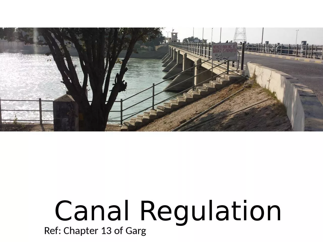
/
Canal Regulation Ref: Chapter 13 of Garg Canal Regulation Ref: Chapter 13 of Garg

Canal Regulation Ref: Chapter 13 of Garg - PowerPoint Presentation

miller
miller . @miller
Follow
66 views
Uploaded On 2023-10-28

Canal Regulation Ref: Chapter 13 of Garg - PPT Presentation

Canal Regulation Regulation Water that enters into the main canal from the river has to be divided into different Branches and Distributaries in accordance with the relative urgency of demand on different channels ID: 1026155

canal channel head regulator channel canal regulator head water cross gates main called parent control escape operated irrigation channels

Share:

Link:

Embed:

Download Presentation from below link

Download Presentation The PPT/PDF document "Canal Regulation Ref: Chapter 13 of Garg" is the property of its rightful owner. Permission is granted to download and print the materials on this web site for personal, non-commercial use only, and to display it on your personal computer provided you do not modify the materials and that you retain all copyright notices contained in the materials. By downloading content from our website, you accept the terms of this agreement.


Presentation Transcript

1. Canal RegulationRef: Chapter 13 of Garg

2. Canal RegulationRegulation Water that enters into· the main canal from the river has to be divided into different Branches and Distributaries, in accordance with the relative urgency of demand on different channels. This process of distribution is called 'Regulation'. To distribute water effectively, the discharge has to be adjusted to any desired value. This aim is achieved by means of regulators

3. Canal Regulation WorksThe works which are constructed in order to control and regulate discharges, depths, velocities etc. in canals, are known as canal regulation works. These structures ensure the efficient functioning of a canal irrigation system, by giving full control upon the canals. The important of these structures are :Canal Falls.Canal Regulators (Head Regulator and Cross Regulator).Canal Escapes.Metering Flumes, etc.

4. Ref: https://www.slideshare.net/muthukumaratvit/design-of-canal-regulator-using-html/2

5. CANAL REGULATORSAlignment of the off-taking channel:When a branch channel takes off from the main channel (called Parent Channel),the off-take alignment must be carefully designed.The best ideal alignment is:When the off-taking channel makes zero angle with the parent channel initially and then separates out in a transition, as shown in Fig. 13.1.The transitions will have to be properly designed, so as to avoid accumulation of silt jetty.

6. As an alternative to the transitions:Both the channels should make an angle with the parent channel upstream of the off-take, as shown in Fig. 13.2.CANAL REGULATORS

7. When the parent channel has to be carried straight, the edge of the canal rather than the centre line should be considered in deciding the angle of the off-take (Fig. 13.3).CANAL REGULATORS

8. Distributary Head Regulator and Cross RegulatorA distributary head regulator controls the supply of the off-taking channel ; while a cross-regulator controls the supply of the parent channel.A head regulator provided at the head of the off-taking channel, controls the flow of water entering this new channel. While a cross-regulator may be required in the main parent channel down-stream of the off-taking channel, and is operated when necessary so as to head up water on its upstream side, thus to ensure the required supply in the off-taking channel even during the periods of low flow in the main channel.

9. The main functions of a head regulator(i) To regulate or control the supplies entering the off-take channel.(ii) To control silt entry into the off-take channel.(iii) To serve as a meter for measuring discharge.

10. Main functions of a cross-regulator(i) To effectively control the entire Canal irrigation System.(ii) When the water level in the main channel is low, it helps in heading up water on the u/s and to feed the off-take channels to their full demand in rotation.(iii) They help in absorbing fluctuations in various sections of the canal system, and in preventing the possibilities of breaches in the tail reaches.(iv) Cross regulator is often combined with a road bridge, so as to carry the road which may cross the irrigation channel near the site of the cross regulator. It is also usually combined with a fall (if required at the site of cross regulator); when it is called a fall-regulator.

11. Components of RegulatorPiers, Gates, BridgeA regulator essentially consists of piers placed across the canal at regular intervals with openings in which either planks or gates can be used to control the supplies. Planks called Karries can be used_for small channels only, as the maximum height of the plank that be handled manually is about 2 metres. For large channels, either hand operated or mechanically operated gates can be used.The hand operated gates can have spans of 6 to 8 m, while mechanically operated gates. can be as wide as 20 metres or so. A light bridge platform has to be laid on the piers for operation of planks or gates. It is often economical to combine a regulator with a bridge and also to flume the channel at the site of the regulator, so as to reduce its floor width for affecting economy.

12. CANAL ESCAPESEscape (or escape regulator) is a side channel constructed to remove surplus water from an irrigation channel (main canal, branch canal, or distributary, etc.) into a natural drain. The water in the irrigation channel may become surplus due to some mistake; or-difficulty in regulation at the head; or due to-excessive rainfall in upper reachesSometimes, the cultivators may find that the demand of water is over and may close their outlets suddenly, in such circumstances, the canal supplies shall become surplus, and this excess may overflow the banks unless escaped.No doubt, in all such circumstances, the supplies shall be reduced or stopped from the head works, but the effect of this reduction is felt only after a certain time. Therefore, in order to avoid damage, some immediate action is required, and this is achieved by means of an 'Escape', generally called a 'surplus water escape'.Escape can considered as Safety Valve for canalTwo Types: Weir Type Escape (Crest level of weir is kept at FSL of canal. No gates)Regulator Type (Crest level of escape is kept at Bed of canal, and gates are used to regulate)

13.

14. METERING FLUMESA meter is a structure constructed in a canal for measuring its discharge accurately.A metering flume is an artificially flumed (narrowed) section of the channel, which can be utilized for calculating the discharge in the channel.Normal section of channel is narrowed by masonary walls by splay of 1 : 1 to 2 : 1 to a rectangular section called Throat. From where, the channel is slowly diverged so as to attain its normal section by means of masonry wings with a splay of 2 : 1 to 10 : 1. More gradual the convergence and divergence, less will be the loss of head in the flume.

15. Types of Meter FlumesVenturi FlumeIt consists of a gradually contracting channel leading to 'throat', and a gradually expanding channel leading away from it.Stilling wells are provided for measuring head at the entrance and at the throat, as shown in Fig. 13.11.If h is head difference in two wells, Q can be calculated as:

16. Types of Meter FlumesStanding Wave FlumeIf a hydraulic jump is formed on d/s glacies, it is called as Standing Wave FlumeIf H is head above crest, Q can be found as:

17. ThanksRef: Hydraulic Structures, by SK Garg, Chapter 13