/
Production Engineering Department, Tokyo Gas Co., Ltd., Tokyo Email:w_ Production Engineering Department, Tokyo Gas Co., Ltd., Tokyo Email:w_

Production Engineering Department, Tokyo Gas Co., Ltd., Tokyo Email:w_ - PDF document

min-jolicoeur
min-jolicoeur . @min-jolicoeur
Follow
431 views
Uploaded On 2016-08-03

Production Engineering Department, Tokyo Gas Co., Ltd., Tokyo Email:w_ - PPT Presentation

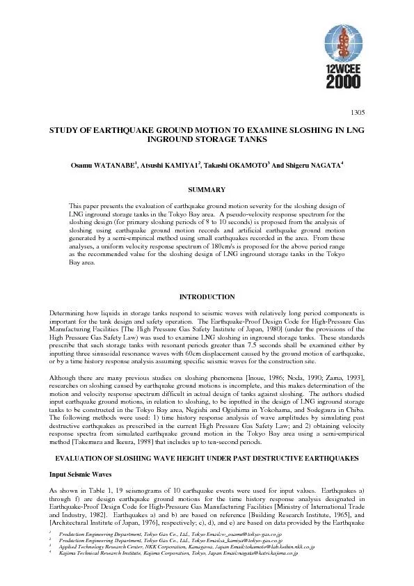
1305Research Institute University of Tokyo Tanaka et al 1979 and f is corrected data of the 1978 Miyagikenoki earthquake recordKurata et al 1979 using the filter proposed by Goto et alG ID: 431195

1305Research Institute University Tokyo

Share:

Link:

Embed:

Download Presentation from below link

Download Pdf The PPT/PDF document "Production Engineering Department, Tokyo..." is the property of its rightful owner. Permission is granted to download and print the materials on this web site for personal, non-commercial use only, and to display it on your personal computer provided you do not modify the materials and that you retain all copyright notices contained in the materials. By downloading content from our website, you accept the terms of this agreement.


Presentation Transcript

Production Engineering Department, Tokyo Gas Co., Ltd., Tokyo Email:w_osamu@tokyo-gas.co.jpProduction Engineering Department, Tokyo Gas Co., Ltd., Tokyo Email:a_kamiya@tokyo-gas.co.jpApplied Technology Research Center, NKK Corporation, Kanagawa, Japan Email:tokamoto@lab.keihin.nkk.co.jp 1305Research Institute, University of Tokyo [Tanaka et al., 1979]; and f) is corrected data of the 1978 Miyagi-ken-oki earthquake record[Kurata et al., 1979] using the filter proposed by Goto et al.[Goto et al., 1978]. Seismicrecord g) came from Nasu and Morioka [Nasu et al., 1973], and records h) through k) came from records ofstrong-motion seismograph of the Japan Meteorological Agency (JMA). The motion of the 1983 Nihonkai-Cyubu earthquake overshot the capacity of the seismograph; hence, lost parts of the waveforms were added later[Okamoto et al., 1984]. Seismic records l) through q) were based on records of the JMA model 87 strong-motion digital acceleration seismograph [Zama et al., 1994]. Seismic records r) and s) came from the Committeeof Earthquake Observation and Research in the Kansai Area. In addition, seismic waves were input at the levelsgiven in the original records.Analytical method and specifications of storage tanks for analysisSloshing-wave responses of the tanks were determined by the axisymmetric linear potential theory with anassumed damping ratio of 0.5 %, and up to the tenth sloshing mode. The tanks for the analysis were six types ofinground storage tanks for LNG in the Tokyo Bay area. Table 1 shows the specifications on these tanks and theirprimary to tertiary sloshing resonant periods. The design depth of liquid in the table is defined as the maximumoperational depth of the liquid in a tank in which clearance between the liquid surface and the tank roof becomesthe minimum.Analysis ResultsTable 1 shows the maximum sloshing wave height for each seismic wave and storage tank. When NS and EWcomponents were recorded from an earthquake, the maximum sloshing wave height was calculated bysynthesizing the two components of the sloshing wave time histories [Zama, S. and Inoue, R., 1994], and is alsoincluded in Table 1. Figure 1 shows some results obtained in the time history response analysis of the sloshingwave height at the tank walls. Figure 2 shows some sloshing modes. The response analysis revealed thefollowing:1) For the 1964 Niigata earthquake (in Kawagishi), the secondary mode dominated such that the maximumamplitude occurred at the tank center instead of the wall (Fig. 2(a)).2) For the 1923 Great Kanto earthquake, the liquid sloshed in the primary mode in all storage tanks (Fig. 2(b)).3) For the 1983 Nihonkai-Cyubu earthquake, the initial sloshing varied by tank; it usually increased thendecreased, and increased again in some tanks, but almost always in the primary mode for all storage tanks(Figs. 1(a) and 2(c)).4) For the 1993 Hokkaido Nansei-oki earthquake, liquid sloshed mostly in the primary mode for all tanks (Figs.1(b) and 2(d)).5) For the 1995 Hyogo-ken Nanbu earthquake, primary mode sloshing overlapped with higher modes (Figs. 1(c)and 2(e)).Figure 3 shows the velocity response spectrum values, , obtained by inverse calculations from the primaryresonant period, , of the storage tank, and the sloshing wave heights, . The are calculated from therelationship between the velocity response spectra [The Japan Gas Association, 1981] and sloshing wave heightsgiven by with where is the liquid level (m), is the tank radius (m), is the gravitational acceleration, and (T, h) is thevelocity response spectrum value (cm/s) for the period T(s) and damping ratio This figure also has the velocity response spectrum values obtained by inverse calculations from the sloshingwave heights given by Eq. (3) [The High Pressure Gas Safety Institute of Japan, 1980]. These calculations werederived from three sinusoidal wave resonance method, a currently used design method prescribed in the HighPressure Gas Safety Law. 1305 where is the amplitude (cm) of displacement. was 60 cm when the resonant period was above 7.5 secondsand equal to cm otherwise.The velocity response spectrum values obtained by inverse calculations from the sloshing wave heights, whichthemselves came from time history response analysis, was about 180 cm/s (Fig. 3). This is significantly smallerthan that obtained by the height calculation formula based on 60cm three sinusoidal wave resonance method assuggested by the High Pressure Gas Safety Law.Table 1: Storage tank specifications and sloshing wave height123456SodegauraOgishimaSodegauraNegishiNegishiSodegauraS-1O-1S-2N-1N-2S-360200602009513032.036.030.034.032.032.018.749.221.355.129.540.40.5841.3670.7101.6170.9221.263primary (s)9.408.938.728.668.658.45secondary (s)4.935.224.765.074.924.92tertiary (s)3.894.123.764.013.893.89a)1.761.961.021.541.241.32b)0.460.540.470.530.500.51c)0.270.330.380.410.390.29d)0.300.400.340.390.370.41e)0.220.260.200.200.210.18f)0.340.410.390.420.410.43g)1.491.300.880.890.830.85h)1.351.801.561.801.681.45i)0.650.891.361.781.671.76j)0.240.220.200.310.270.33k)0.520.720.610.670.620.46l)3.123.673.133.593.303.17m)1.341.281.071.271.191.28n)2.141.070.840.920.871.10o)0.980.680.690.790.750.96p)0.550.770.760.840.790.82q)0.861.361.221.431.311.27r)0.811.080.951.181.181.13s)1.021.181.131.221.181.241974 Izu-hanto-oki (Tokyo University, Hongo)0.370.470.380.430.420.441983 Nihonkai-Chubu (Niigata)1.361.931.601.861.751.881964 Niigata (Akita)0.530.720.610.680.630.511993 Hokkaido Nansei-oki (Tomakomai)3.193.803.223.703.413.291993 Hokkaido Nansei-oki (Niigata)2.141.190.991.081.011.281993 Hokkaido Nansei-oki (Akita)0.951.461.361.601.491.491995 Hyogo-ken Nanbu (Amagasaki)1.271.581.451.641.581.616.578.207.178.267.778.15Tank No.LocationTank labelCapacity (1000 mRadius :R (m)Design depth :H (m)H/RResonantperiodEarth uakeSloshing wave height :  (m)1964 Niigata (Kawagishi) NS1968 Tokachi-oki (Hachinohe) EW1933 Sanriku-oki (Tokyo University, Hongo) NS1974 Izu-hanto-oki (Tokyo University, Hongo) NS1974 Izu-hanto-oki (Tokyo University, Hongo) EW1978 Miyagi-ken-oki (Shiogama port) EW1923 Great Kanto (Tokyo)1983 Nihonkai-Chubu (Niigata) NS1983 Nihonkai-Chubu (Niigata) EW1964 Niigata (Akita) NS1964 Niigata (Akita) EW1993 Hokkaido Nansei-oki (Tomakomai) NS1993 Hokkaido Nansei-oki (Tomakomai) EW1993 Hokkaido Nansei-oki (Niigata) NS1995 Hyogo-ken Nanbu (Amagasaki) EW 60cm three sinusoidal wave resonance method1993 Hokkaido Nansei-oki (Niigata) EW1993 Hokkaido Nansei-oki (Akita) NS1993 Hokkaido Nansei-oki (Akita) EW1995 Hyogo-ken Nanbu (Amagasaki) NS (a) 1983 Nihonkai-Cyubu (Niigata) NS (b) 1993 Hokkaido Nansei-oki (c) 1995 Hyogo-ken Nanbu(Tomakomai) NS (Amagasaki) EWFigure 1: Time history of sloshing wave 1305 (c) 1983 Nihonkai-Chubu (Niigata) NSTank No.6 (S-3) -2 (a) 1964 Niigata (Kawagishi) NSTank No.2 (O-1) -2 (e) 1995 Hyogo-ken Nanbu (Amagasaki) EWTank No.4 (N-1) -1 (d) 1993 Hokkaido Nansei-oki (Tomakomai) NSTank No.2 (O-1) -4 (b) 1923 Great Kanto (Tokyo)Tank No.1 (S-1) -2 Figure 2: Sloshing modesEVALUATION OF EARTHQUAKE GROUND MOTION FOR TOKYO BAY AREAAnalytical MethodMany predictions of earthquake ground motion using the semi-empirical method have been proposed. Theauthors used the semi-empirical method [Takemura and Ikeura, 1988], taking into account irregular slips of thefault plane, to simulate earthquake ground motion with the primary periods up to 10 seconds for storage tanks inthe Tokyo Bay area. This method is applicable to the simulation of earthquake ground motion with periods up toaround 10 seconds if earthquake events and their seismograms are carefully selected.Our procedure for the earthquake strong ground motion evaluation by the semi-empirical method was thefollowing:1) Select element earthquakes and element seismic waves.2) Examine the effective period range of the element seismic waves.3) Remove the effects of the ground surface layers from the element seismic waves.4) Synthesis of strong ground motions.Earthquake Assumptions and Regions AnalyzedUpon selecting the sites in Tokyo Bay area for evaluation, three other regions of high earthquake hazardpotential were analyzed [Zama, 1991; Zama, 1993]; 1) the offshore region from Niigata to Akita along theeastern shore of the Japan Sea, 2) off the Boso Peninsula, and 3) around the Izu Peninsula. For these regions, wefound the following great past earthquakes relevant for analysis: the 1983 Nihonkai-Cyubu earthquake (M =7.7), the 1605 Tokai earthquake from the fault on the north side (M = 7.9), and the 1978 Izu-Oshima earthquake(M = 7.0). Furthermore, South Kanto and Tokai, which have established disaster prevention measures inanticipation of great earthquakes, need further study because the forces from earthquake components of longperiods have not yet been adequately studied. Therefore, we included hypothetical South Kanto and Tokaiearthquakes with JMA magnitudes of 7.9 and 8.0, respectively. The 1983 Nihonkai-Cyubu earthquake wasomitted because reliable accelerograms with periods up to 10 seconds were already observed at Negishi. 51015100200300400500 Velocity response spectrum (cm/s)Period (s) Tank No.1 (S-1) Tank No.2 (O-1) Tank No.3 (S-2) Tank No.4 (N-1) Tank No.5 (N-2) Tank No.6 (S-3) 60cm three sinusoidal wave resonance method 1964 Niigata (Kawagishi) NS 1968 Tokachi-oki (Hachinoe) EW 1978 Miyagi-ken-oki (Shiogama port) EW 1933 Sanriku-oki (Tokyo University, Hongo) NS 1974 Izu-hanto-oki (Tokyo University, Hongo) 1923 Great Kanto (Tokyo) 1983 Nihonkai-Chubu (Niigata) 1964 Niigata (Akita) 1993 Hokkaido Nansei-oki (Tomakomai) 1993 Hokkaido Nansei-oki (Niigata) 1993 Hokkaido Nansei-oki (Akita) 1995 Hyogo-ken Nanbu (Amagasaki) Figure 3: Primary resonant periods Figure 4: Assumed earthquake faultsand velocity response spectraand evaluation sites 1305Figure 4 shows the locations of fault planes for these five earthquake scenarios and evaluation points in theTokyo Bay area, while Table 2 has parameters of the faults. Previous studies [Kanamori, 1971; Ishibashi, 1981;Aida, 1981; Simazaki and Somerville, 1979] were referred to determine these parameters, types, and startingpoints of ruptures. They were selected so earthquake components with periods of 8 to 10 seconds predominatedas much as possible.Table 2: Fault parameters for earthquake scenariosEarthquakeLengthWidthDepth tofault topStrikeDipSlipSeismicmomentRupturevelocityRiseTimeRupture mode(km)(km)(km)(x10dynecm)(km/s)(s)Hypo.South Kanto1307052903416276.03.05.0Unilateral rupturestarting from west endHypo. Tokai120502198206090.02.78.6Radial rupturestarting from center of west endHypo.Boso-hanto-oki150100128730154530.03.05.0Unilateral rupturestarting from east endHypo.Izu-Oshima17102270851881.13.02.5Unilateral rupturestarting from west end(degree) Selection of Earthquake Events and their Seismograms Used in Semi-empirical MethodIn a semi-empirical method, the focal characteristics and similarity of wave propagation of small earthquakeevents are used to estimate ground motion, earthquake events and their seismic waves were selected according tothe following.1) medium and small earthquakes that occurred inside or around the earthquake faults and, more importantly,had similar propagation path.2) seismic waves at the evaluation points or from adjacent areas with similar ground conditions.3) earthquakes with JMA magnitude above 4 as an element earthquake, because the law of similarity for faultparameters is usually applied only when the element earthquake has seismic moments greater than 1022dynes.4) as far as practicable, earthquakes with a shallow focus which are more likely to stir up surface waves, whichare dominant and exert influence on sloshing.5) seismic waves with effective periods that are smaller than 10 seconds.After that, the authors define the earthquake events and their seismic waves by removing the effects of theground surface layers on the layer upon which the tanks lie from seismic waves observed at the surface and thisrequires determination of incident waves (2E) on hypothetical open bedrock.Analysis ResultsIn the semi-empirical method, the degree of heterogeneity of displacement on fault plane is provided withnormal random numbers (mean = 0.0, standard deviation = 1.0), such that the similarity law of earthquake inaccordance with the model. Then we prepared 10 to 30 sample accelerograms for each horizontalcomponents observed at the three study locations, and calculated their pseudo-velocity response spectra(damping ratio: 0.5 %). In addition, the calculation of earthquake ground motion for the points in Negishi,Ogishima and Sodegaura was conducted at bedrock, which is affected limitedly by ground nonlinearities duringa great earthquake.Figure 5 compares six pseudo-velocity response spectrum for Negishi, Ogishima, and Sodegaura in hypotheticalSouth Kanto and hypothetical Tokai earthquakes with more remarkable than those in the other simulatedearthquakes. Each curve in the figure is the envelope of the pseudo-velocity response spectra (damping ratio: 0.5%) calculated from accelerograms with NS and EW components for each site which were obtained by the semi-empirical method.Previous studies reported that the predominant sloshing periods in the central area differed from those at therecess of the Tokyo Bay area [Niwa et al., 1990; Zama, 1990; Niwa et al., 1993]. We found the dominant peakperiods were about 6 or 6.5 seconds at Negishi and Ogishima (in the central area), and around 1, 6, and 8seconds at Sodegaura (in the recess), in qualitative agreement with the previous reports. However, despite these 1305differences in period of the pseudo-velocity response spectrum, the maximum values of the envelopes for thethree sites were all around 150 cm/s at periods of 8 to 10 seconds. These are the primary sloshing periods for60,000 to 200,000m tanks, a common size for tanks in the Tokyo Bay area.Additional curves presented for reference in Figure 5 are the results of the pseudo-velocity response spectrumevaluation by the normal mode method [Kudo, 1980], a theoretical method commonly used by previous studieson earthquake ground motion with relatively long periods. We found that this method gave similar results to thesemi-empirical method. (a) Hypothetical South Kanto earthquake(b) Hypothetical Tokai earthquakeFigure 5: Pseudo-velocity response spectra (damping ratio is 0.5 %)Spectra in the Tokyo Bay AreaFigure 6 shows the maximum envelopes of those pseudo-velocity response spectra (damping ratio: 0.5 %) forfive earthquake scenarios that were obtained using the semi-empirical method; however, the spectra of the 1983Nihonkai-Cyubu earthquake was determined using accelerograms observed at Negishi. The hypothetical SouthKanto earthquake had its maximum envelope peak between 8 and 10 seconds (which is the primary sloshingperiod of many LNG inground storage tanks); its maximum value was approximately 150 cm/s. Figure 6: Characteristics of pseudo-velocity response spectra containing components with periods up to 10seconds in the Tokyo Bay area (damping ratio is 0.5 %) 1305Also Figure 6 shows the envelopes of the pseudo-velocity response spectra from this analysis comparing withthe following design spectra for ground motion considering periods up to 10 seconds:a) the spectrum derived from the Earthquake-Proof Design Code for High-Pressure Gas Manufacturing Facilities[Subcommittee for Seismic Countermeasures of High-Pressure Gas and Explosives Security Council, 1980];this was determined by the 60cm three sinusoidal wave resonance method and satisfied the High Pressure GasSafety Law,b) the spectrum derived from Fire Services Law [Udoguchi, 1988],c) the spectrum specified by American Petroleum Institute [API, 1996], andd) the spectrum of the standard earthquake ground motion for high-rise buildings in the Tokyo Bay area [Niwa,1993].For periods of 8 to 10 seconds, the envelopes from this study exceeded spectra from b), c), and d) aboveparagraph. Those spectra all were converted by a simplified formula into spectra of 0.5 % damping ratio. Inaddition, this analysis showed that the velocity response spectra obtained by 60cm three sinusoidal waveresonance method are about 2 to 3 times as intense as those assumed for the Tokyo Bay area for periods between8 and 10 seconds.CONCLUSIONFocus on typical sites of LNG inground storage tanks in the Tokyo Bay area, we evaluated the velocity responsespectra based on the results obtained from the time history response analysis under past destructive earthquakes,and simulated earthquake ground motion including components with periods up to about 10 seconds. Resultswith past destructive earthquakes in section 2, together with the normal mode analysis in section 3, suggestedthat 180cm/s is an indicator of the velocity response spectrum value used to examine sloshing of ingroundstorage tanks in Tokyo Bay area that have primary sloshing periods of 8 to 10 seconds. To summarize theresults:1.The time history response analysis of the sloshing from past destructive earthquakes showed that thevelocity response spectrum value with a maximum near 180cm/s was significantly smaller than thatbased on 60cm three sinusoidal wave resonance method suggested by the High Pressure Gas SafetyLaw.2.Of all pseudo-velocity response spectra simulated by semi-empirical method, only the hypotheticalSouth Kanto earthquake's maximum envelope reached its maximum for periods between 8 and 10seconds; this maximum was approximately 150cm/s. This range of resonant periods is typical of majorLNG inground storage tanks in the Tokyo Bay area.3.The authors found maximum envelopes of the pseudo-velocity response spectra greater or equal to thosefrom previous studies about major velocity response spectra. In particular, the spectrum simulated bysemi-empirical method for periods between 8 and 10 seconds were 2 to 3 times as intense as thoseobtained by 60cm three sinusoidal wave resonance method, a method suggested by the current HighPressure Gas Safety Law.REFERENCESAPI (1996), “Design and construction of large, welded, low-pressure storage tanks”, API Standard 620, NinthEditionAida, I. (1981), “Numerical experiments of historical tsunamis Generated off the coast of the Tokaido district”,Bull. Earth. Res. Inst., University of Tokyo, 56(2), pp367-390 (in Japanese with English abstract)Architectural Institute of Japan (1976), “Corrected waveforms of strong motion record (in the Tokachi-okiearthquake in 1968) at the Hachinohe port”, Journal of Architecture and Building Science, 91, 1107 (inJapanese).Building Research Institute, Ministry of Construction (1965), “Niigata earthquake and damage to reinforcedconcrete buildings in Niigata city”, Report of the Building Research Institute, 42 (in Japanese).Goto, H., Kameda, H., Sugito, M. and Imanishi, N. (1978), “Correction of SMAC-B2 accelerograph records bydigital filter”, Proceedings of the Japan Society of Civil Engineers, 227, pp57-69 (in Japanese).Inoue, R. (1986), “Studies on design earthquakes in the period of 2 to 20 sec –A review”, Proceedings of theJapan Society of Civil Engineers, Structural Engineering/Earthquake Engineering, 374/I-6, pp1-23 (inJapanese). 1305Ishibashi. K. (1981), “Specification of a soon-to-occur seismic faulting in the Tokai district, central Japan, basedupon seismotectonics, Maurice Ewing Series Vol.4Am. Geophys. Union, pp297-332.Kanamori, H. (1971), “Faulting of the great Kanto earthquake of 1923 as revealed by seismological data”, Bull.Earth. Res. Inst., University of Tokyo, 49, pp13-18.Kudo, K. (1980), “A study on the contribution of surface waves to strong ground motions”, Proc. 7th WCEEIstanbul, pp499-506.Kurata, E., Iai, S., Yokoyama, Y., and Tsuchida H. (1979), “Strong-motion earthquake records on the1978Miyagi-ken-oki Earthquake in port areas”, Technical Note of Port and Harbor Research Institute, Ministry ofTransport, Japan, 319.Ministry of International Trade and Industry (1982), Notification No.23.Nasu, S. and Morioka T. (1973), “Ground Motion in Violent Earthquakes (5)”, The Kenchiku Gijutsu, 267,pp241-247 (in Japanese).Niwa, M. (1993), “Part 1: Input ground motion for aseismic design of high-rise buildings, (1) StandardEarthquake ground motion and Its Application”, Kenchiku Bousai, pp4-9.Niwa, M., Ohbo, N., Suzuki, Y., and Nozawa, T. (1990), “Earthquake ground motion characteristics in Tokyobay area – Part 1 Study on long period ground motion in records of the 1990.2.20 near Izu-Ohshima earthquake”,Summaries of Technical Papers of Annual Meeting - Structures IArchitectural Institute of Japan, pp347-348 (inJapanese).Niwa, M., Yamanaka, H., Takemura, M., and Ikeura, T. (1993), “Earthquake ground motion characteristics inTokyo bay area – Part 6 Study on long period ground motion during the Noto-hanto-oki earthquake on Feb.7,1993”, Summaries of Technical Papers of Annual Meeting - Structures I Architectural Institute of Japan, pp175-176 (in Japanese).Noda, S. (1990), “Review and future prospect of prediction methods of long-period (2 – 20 sec) groundmotions”, Proceedings of the 18th Symposium on Ground Vibration, Architectural Institute of Japan, pp45-54(in Japanese with English abstract).Okamoto, T. and Sakaki, N. (1984), “The Height of Sloshing wave-height of oil-tank at the time of Nihonkai-chubu earthquake”, Proceedings of the 39th Annual conference of the Japan Society of Civil Engineers, I-350,pp699-700 (in Japanese).Simazaki, K. and Somerville, P. (1979), “Static and dynamic parameters of the Izu-Oshima, Japan, earthquake ofJanuary 14, 1978”, Bull. Seism. Soc. Am., 69, pp1343-1378.Takemura, M. and Ikeura, T. (1988), “A semi-empirical method using a hybrid of stochastic and deterministicfault models: simulation of strong ground motions during large earthquakes”, J. Phys. Earth, 36, pp89-106.Tanaka, T., Yoshizawa, S., and Osawa, Y. (1979), “Characteristics of Strong Earthquake Ground Motion in thePeriod Range from 1 to 15 Seconds”, Bull. Earth. Res. Inst., University of Tokyo, 54, pp629-655 (in Japanesewith English abstract).The High Pressure Gas Safety Institute of Japan (1997), “Earthquake-proof design code for high-pressure gasmanufacturing facilities”, The High Pressure Gas Safety Institute of JapanThe Japan Gas Association (1981), “Recommended practice for LNG above ground storage”, The Japan GasAssociationUdoguchi, T. (1988), “On the guideline for seismic design of oil storage steel tanks included in JIS B 8501 –1985 Welded steel tanks for oil storage”, Journal of High Pressure Institute of Japan, 26, 5, pp47-55 (inJapanese with English abstract).Zama, S. (1990), “Predominant periods of long period ground motion”, Report of Fire Research Institute of, 70, pp1-7 (in Japanese with English abstract).Zama, S. (1991), “A study on the regional differences in the characteristics of long-period strong ground motionsobserved by JMA strong motion seismograph (Part 1)”, Report of Fire Research Institute of Japan, 72, pp11-23(in Japanese with English abstract).Zama, S. (1993), “Characteristics of long-period strong ground motions observed by JMA strong motionseismograph (Part 2: Tokyo)”, Report of Fire Research Institute of Japan, 76, pp1-11 (in Japanese with Englishabstract).Zama, S. (1993), “Long-period strong ground motion”, ZISIN, 46, pp329-342 (in Japanese).Zama, S. and Inoue, R. (1994), “Sloshing of liquid in oil storage tanks due to the 1993 Hokkaido Nansei-okiearthquake”, Report of Fire Research Institute of Japan, 77, pp1-10 (in Japanese with English abstract).