/
E. Follow-up discussion on Parallel CT clarification per SM E. Follow-up discussion on Parallel CT clarification per SM

E. Follow-up discussion on Parallel CT clarification per SM - PowerPoint Presentation

mitsue-stanley
mitsue-stanley . @mitsue-stanley
Follow
392 views
Uploaded On 2017-05-26

E. Follow-up discussion on Parallel CT clarification per SM - PPT Presentation

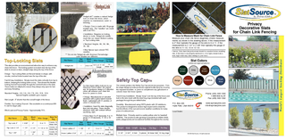
SMOG 137 e Paralleling of Current Transformers Connected burden Paralleling of current transformers is not recommended However when it is necessary the following requirements apply ID: 552675

parallel burden common current burden parallel current common meter cts smog test paralleling transformers impedance secondary transformer data due

Share:

Link:

Embed:

Download Presentation from below link

Download Presentation The PPT/PDF document "E. Follow-up discussion on Parallel CT c..." is the property of its rightful owner. Permission is granted to download and print the materials on this web site for personal, non-commercial use only, and to display it on your personal computer provided you do not modify the materials and that you retain all copyright notices contained in the materials. By downloading content from our website, you accept the terms of this agreement.


Presentation Transcript

Slide1

E. Follow-up discussion on Parallel CT clarification per SMOG 1.3.7 (e) (H. Perez)SMOG 1.3.7 (e) Paralleling of Current Transformers – Connected burdenParalleling of current transformers is not recommended. However, when it is necessary, the following requirements apply.(e) Each current transformer must be capable of supporting n times the common burden plus its own individual burden and stay within the accuracy class of the transformers, where n = number of current transformers in parallel. This is the effective burden for each current transformer.

Slide2

Open item questions regarding paralleling of CTs:How to verify individual impedance on each conductor and common impedance? measure or calculate. Per SMOG 1.3.7(c) “The secondary circuits shall be parallel at the meter test switch”. Thus, the only common impedance is the meter panel and meters.Is common burden shared equally between all parallel CTs? Yes, if all CT’s are energized. iii. Should maximum current (at rating factor) be utilized in calculating total burden on each CT in case of flow thru scenarios (eg. Breaker-and-half scheme)? No. Not included in burden design criteria.iv. What is the impact if CT primary is shorted? Erroneous meter data. Reverse current flow thru the CT secondary due to a parallel path to ground. This is not recommended.Slide3

Open item questions regarding paralleling of CTs:What is the impact if CT secondary is shorted? Erroneous meter data. Reverse current flow due to a parallel path to ground. This is not recommended.What was the result of the lab test conducted by CNP? Verified the accuracy of the ERCOT CT Burden Spreadsheet. Per SMOG 1.3.7(c) - “the paralleling at the meter test switch”. The common impedance is very small thus the common burden increases the effective burden on the CTs very little.For parallel CTs, do not short the primary or secondary side of the transformer while still in the metering circuit. It can create erroneous meter data due to the parallel path to ground.The test involved non-typical Z values for cable Z and common Z to illustrate and emphasize the effects of common burden on parallel CT’s.